
Multi-unit slip motor speed control system synchronous operation circuit

The described system incorporates a balanced bridge configuration that collaborates with dancers to achieve precise control of motor speeds within a porcelain unit. The sync adjustment rheostat plays a critical role in fine-tuning the speed control system, which is visually represented in the referenced figure. The electro-magnetic and photoelectric dancers operate under a similar principle, utilizing the main motor (BQ2) to establish a slip reference speed through its field winding.
The orientation of BQi and BQ3 is strategically designed to manage the slip of the motor's field winding effectively. The RPz potentiometer is essential for adjusting the overall speed of the system, allowing for flexibility in the operation of three motors simultaneously. Each motor's slip can be finely tuned, thanks to the integration of tachometer generators (TGi to TG3), which are connected to the electromagnetic slip clutch shafts of the respective motors.
The adjustment potentiometers (1RP1, 2RP1, 3RP1) are vital for modifying the negative feedback voltage associated with each motor's slip speed, providing a mechanism for dynamic speed adjustments. Furthermore, the sensitivity potentiometers (1RP2, 2RP2, 3RP2) allow for precise alterations to the slip speeds, enhancing the responsiveness of the system to changes in operational conditions.
The dish rheostats (RP., RPb) serve a crucial function in synchronizing the slip speeds of the three motors, ensuring that they operate in unison. This synchronization is vital for applications where coordinated movement is required, enhancing the overall performance and reliability of the system. The combination of these components creates a sophisticated speed control system that can adapt to varying operational demands while maintaining precise control over motor performance. Collaboration with the dancers balanced bridge long on the porcelain unit Sync adjustment rheostat speed control system shown in Figure 3 to 183 in FIG. Others, such as electro magnetic, photoelectric dancers speed control principle is similar. FIG, BQ2 main motor so that the slip (i.e., as a reference speed) of the field winding, BQi and BQ3 are oriented so that the slip of the front and rear of the motor slip motor field winding. RPz based order potentiometer, which can be adjusted to change the entire system (ie, three motor slip) speed.
TGi ~ TG3 for the three tachometer generator, they are connected with the respective electromagnetic slip clutch shaft of the motor. Adjust potentiometer 1RP1 (2RPi, 3RPl) can change the size of each slip motor speed negative feedback voltage (may cause speed changes).
lRP2 (2RP2,3RP2) the sensitivity potentiometer, which can be adjusted to change a corresponding slip speed of the motor. Dish rheostat RP., RPb to coordinate three slip speed of the motor, so that they run synchronously.
Related Circuits
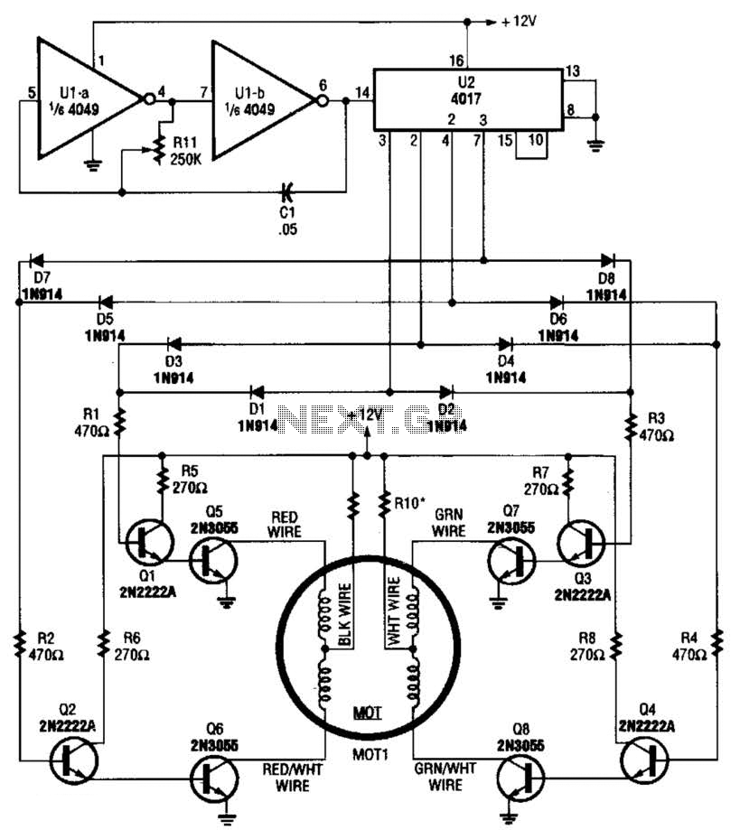
A 4017 decade counter/divider, driven by a low-frequency oscillator (U1-a and U1-b), is employed to control transistor switches that sequence the motor windings as required. The motor (MOT1) is a 12-V stepper motor. Resistors R9 and R10 are chosen...
The power supply has been simplified. Power transformers and rectifiers have been omitted, and some components from the MOSFET voltage regulator circuits have been removed, including 1N5242 zener diodes between the source and gate and 10k resistors in series...
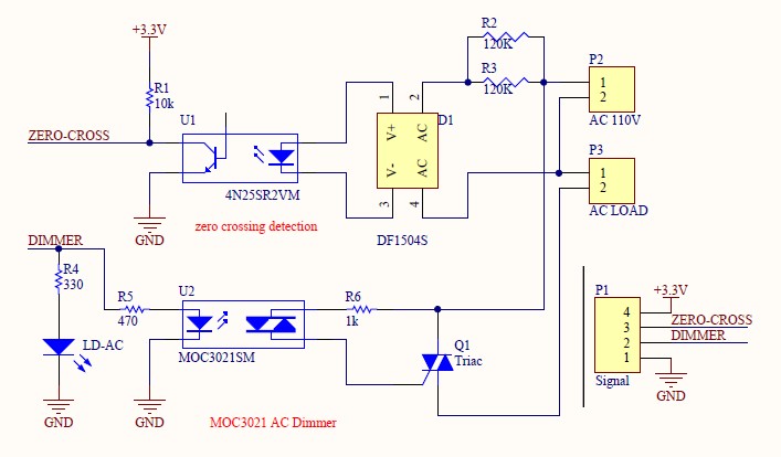
Have you verified whether you can see the zero crossings on your input pin? It may be beneficial to write a sketch that toggles the LED on pin 13 every 50 or 60 zero crossings. This should result in...
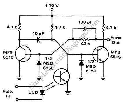
This is a flash-triggered (photo-driven) circuit that produces a pulse with a constant predetermined width. This circuit can be used to control any device. The flash-triggered circuit operates by utilizing a photodetector, which is typically a photodiode or phototransistor, to...
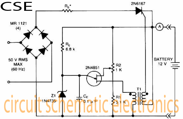
The accumulator charger circuit must provide a voltage that matches the specifications of the batteries being charged. For a 12-volt accumulator, the output voltage should not exceed 12 volts, nor should it fall significantly below this threshold. Failure to...
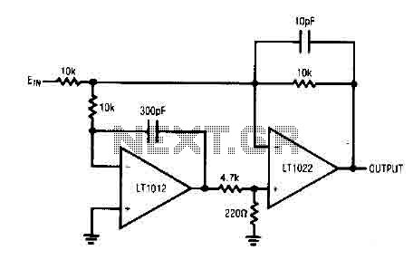
The circuit comprises a low drift LT1012 device and a high-speed amplifier LT1022. It functions as a unity gain inverter, with the summing node located at the junction of three 10k ohm resistors. The circuit monitors the summing node...