
Multi-way pocket alarm circuit

This two-way alarm circuit leverages the characteristics of a Schmitt trigger to provide reliable temperature monitoring with both upper and lower limits. The use of thermistors allows for precise temperature sensing, while the piezoelectric buzzer and LEDs serve as effective alert mechanisms. The design's low power consumption is particularly advantageous for battery-operated applications, ensuring prolonged operation without frequent battery replacements. The versatility of the circuit also allows for modifications, such as integrating different sensing elements, to accommodate various environmental monitoring needs. The schematic design should clearly indicate the connections between the components, including the power supply, input sensors, and output indicators, ensuring ease of assembly and troubleshooting.This is a two-way can set the alarm circuit which uses a Schmitt IC, with responsive and sound and light show, small size, low power consumption, all of the elements is only 13, a very low cost. This circuit is divided into two parts by the A, B and R4, C1 composition limit alarm. And in C, D and R5, C2 constitute the lower limit alarm function, the circuit shown in Figure 1.Usually RP1, RP2 are provided two upper and lower alarm point, the A and C inputs are high, the outputs are low leaving the oscillator are halted. When the temperature is too high, the thermistor resistance R1 decreases, the output high A, B start-up, the piezoelectric ceramic YD a high-pitched beep.
At the same time, the light emitting diode LED1 lights on to indicate overheating. When the temperature is too low, the thermistor R2 resistance increases output high of C, D start-up, the piezoelectric sheet issued YD bass tone beep. Light emitting diode LED2 display temperature is too low.Since CMOS circuit static power consumption is extremely small, only microampere current level, so static power consumption mainly in the RP1, RP2 and thermistors.
If we can use resistance at more than a hundred k special temperature resistance, RP1, RP2 a corresponding increase in the scale drawing press, the static power consumption can be controlled very small, it is extremely beneficial to prolong battery life.Component list as follows: Number Name Type Quantity R1,2 thermistor 1K 2 R3 resistance 3K 1 R4,5 resistance 2M 2 RP1,2 adjustable resistor 10K linear 2 Polyester capacitors C1 300P 1 Polyester capacitors C2 1000P 1 LED1,2 emitting diode µ3mm 1 Schmidt integrated circuit or IC CD4093 MC14093 1 YD piezoelectric buzzer µ20mm HTD20A-1 type 1 E battery lighter dedicated 12V small battery 1 The alarm uses the components is not large, do like so small matchbox.If instead of using photosensitive resistance thermistor can be used as the light intensity alarm. It can also be the other input of the Schmitt trigger use down as light, temperature bifunctional two-way alarm.
It leads to a control signal from the LED fill light, humidification (ultrasonic humidifier) to compose automatically fill light and humidity controller.
Related Circuits

This design outlines a power supply circuit capable of producing a 5V source voltage. The circuit is constructed using TTL integrated circuits (ICs) and features a simple design. In circuits utilizing TTL ICs, the supply voltage is critical, as...
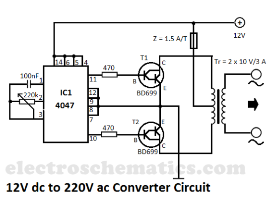
This DIY 12V to 220V voltage converter is built with a CMOS 4047, which serves as the main component for transforming 12V DC into 220V AC. The 4047 operates as an astable multivibrator, generating a symmetrical rectangular signal at...
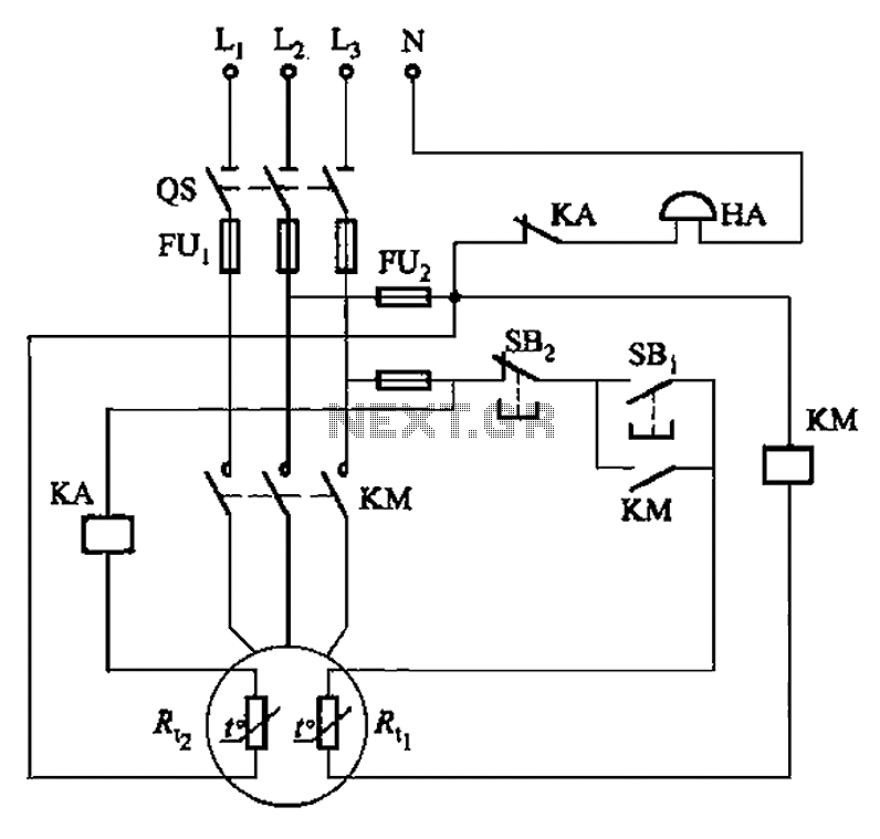
The circuit illustrated in Figure 4-2 employs two thermal resistors. One, designated as Rc, functions as overload protection, while the other, labeled Rt, serves as an alarm. The circuit in question integrates two thermal resistors to monitor temperature changes and...
It came to me in a flash. A simple way to see if a fuse has blown without removing it from its holder. Its not often you can design a circuit using just two components, but with just one...
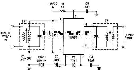
This simple frequency converter mixes the 15-MHz WWV/WVH signal with a 16-MHz signal from the local oscillator (LO) to convert it down to 1 MHz, enabling it to be received on an AM-band receiver. The frequency converter operates by utilizing...
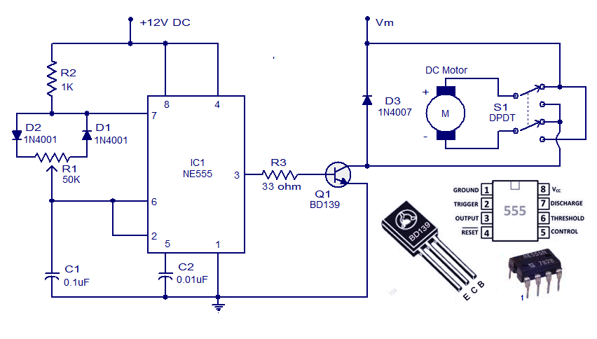
This weblog discusses electronic circuit schematics, PCB design, DIY kits, and electronic project diagrams. A simple DC motor controller circuit utilizing the NE555 timer is presented. Several DC motor speed control circuits are explored, with this being the first...