
Simple Wwv Converter For Auto Radios Circuit

The frequency converter operates by utilizing a mixing process, which is fundamental in radio frequency applications. The circuit employs a non-linear mixer, where the 15-MHz signal from the WWV/WVH source and the 16-MHz signal from the local oscillator are combined. The output of this mixing process generates new frequencies, specifically the sum and difference of the input frequencies.
In this case, the difference frequency is of primary interest. The mixing of the 15-MHz signal and the 16-MHz local oscillator signal produces an output frequency of 1 MHz (16 MHz - 15 MHz = 1 MHz). This frequency is suitable for AM-band reception, making it possible for standard AM radios to pick up the signal.
The circuit may incorporate additional components such as bandpass filters to isolate the desired 1 MHz output and suppress unwanted frequencies generated during the mixing process. Amplification stages may also be included to ensure the output signal is strong enough for effective reception.
Power supply considerations are critical; the circuit requires a stable voltage source to ensure consistent performance of the local oscillator and the mixer. Proper grounding and layout practices should be followed to minimize noise and interference, which can adversely affect the quality of the received signal.
Overall, this frequency converter is a straightforward yet effective solution for down-converting higher frequency signals to a range suitable for AM-band receivers, facilitating the accessibility of specific frequency signals for audio reproduction. This simple frequency converter mixes the 15-MHz WWV/WVH signal with a 16-MHz signal from the LO to convert it down to 1 MHz so that it can be heard on AM-band receiver.
Related Circuits
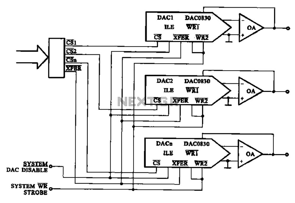
A multi-channel D/A converter circuit is presented, illustrating its fundamental structure. This circuit effectively converts encoded digital signals into multiplexed analog signal outputs. The multi-channel Digital-to-Analog (D/A) converter circuit is designed to facilitate the conversion of digital signals into corresponding...
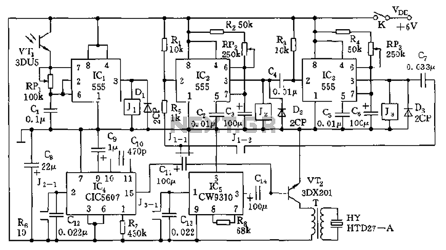
The circuit consists of four light-controlled electronic switches, timing circuits, voice circuits, audio circuits, and other components. It is designed to celebrate birthdays or similar occasions, with features such as birthday candles that can be lit or extinguished. The...
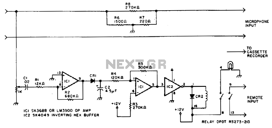
Amateurs do not have to miss the action while away from the rig. This circuit activates a tape recorder whenever the receiver's squelch is broken. After signal loss, the recorder will turn off following a slight delay. The described circuit...
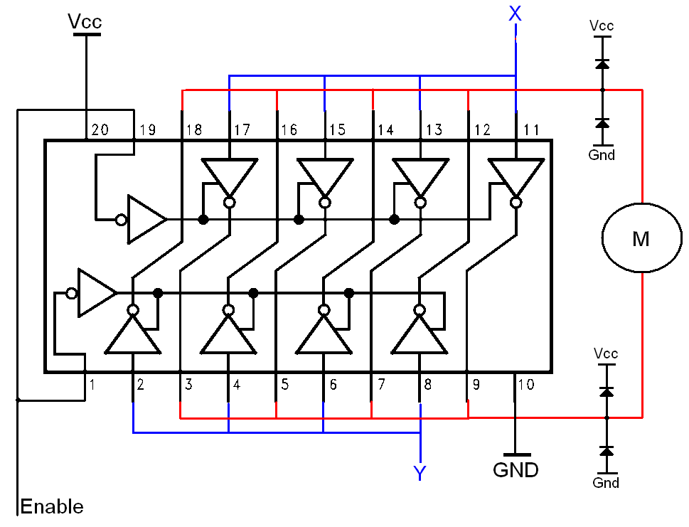
The H-bridge is a well-known and widely used circuit configuration for driving brushed DC motors. It enables straightforward control of motor direction, allowing for both forward and reverse operation. The H-bridge circuit consists of four switches, typically implemented using transistors...
The 1-megohm resistor protects the FET from potential damage caused by accidental sparks to its gate lead. The circuit functions adequately without this resistor; however, it is advised not to intentionally apply a charge to the gate wire using...
High-voltage isolation switches must not be connected to loads that could create an arc, which may lead to a short circuit between the high-voltage bus and result in accidents that endanger both equipment and personnel safety. Consequently, high-voltage switchgear...