
Multiplicative DA converter IC inexpensive 8 DA circuit

The described circuit features an integrated circuit (IC) latch that serves to stabilize and maintain the digital data during the transition of the clock signal. This stabilization is critical in digital systems where timing and data integrity are paramount. The use of the AD7s23 holding data port ensures that the data remains consistent and can be reliably accessed.
The thin film resistor ladder is an essential component of the 8-bit DAC. It comprises a series of resistors that divide the reference voltage into smaller, precise increments, allowing for the conversion of digital signals into corresponding analog voltages. This ladder structure is designed to provide high accuracy and linearity in the output voltage, which is vital for applications requiring precise analog representations of digital data.
The operational amplifier (op-amp) Ai plays a significant role in this circuit by performing the current-to-voltage conversion. This conversion is necessary to translate the digital signal into an analog voltage that can be used in various applications, such as audio processing, signal generation, or control systems. The output voltage, represented as 1XEo, is derived from the digital input data divided by 256 and multiplied by the reference voltage (Va). This formula indicates that the DAC can output a range of voltages corresponding to the 8-bit digital input, which spans from 0 to 255.
Overall, this configuration is well-suited for applications that require precise digital-to-analog conversion, ensuring that the output faithfully represents the input digital data within the specified range. The combination of the IC latch, resistor ladder, and op-amp provides a robust solution for effective data manipulation and signal processing.ICi latch is used to lock the digital data clock signal rises ~ Qu holding data port AD7s23 thin film resistor ladder and c- Jing switch 08 constitute 8-bit DAC, the reference voltage complete set of data and digital multiplication operations. By the current-voltage conversion performed OP amplifier Ai. Output 1XEo as (the digital data / 256) Va, the digital data in the range of 0.255 - the number of projection.
Related Circuits
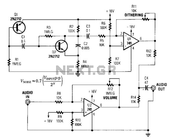
By introducing a small amount of noise to a signal intended for digitization (approximately 0.7 bits), where n represents the number of bits, for instance, an 8-bit signal with a peak-to-peak voltage of 2 V would result in a...
The circuit (before flameout) worked like this: device Q1 is a triac, which is a power-switching device. When triggered, it switches to a fully conducting state and stays that way until the current passing through it goes to zero....
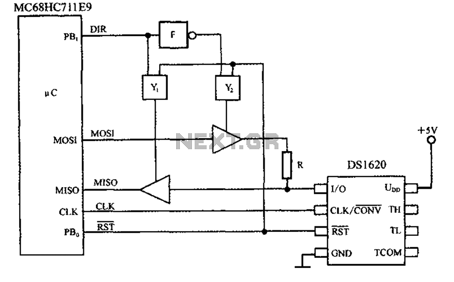
This circuit features a three-wire serial interface for smart temperature sensors, specifically the DS1620, along with an SPI bus interface circuit. The DS1620 is a high-accuracy digital temperature sensor that communicates over a three-wire interface, which consists of a data...
This project involves a 555 buzzer circuit utilizing the NE555 timer IC, which comes in an 8-pin DIP package and performs a wide variety of functions in electronic circuits. The circuit described will produce a buzzer sound when a...

The circuit is designed to fit snugly, eliminating the need for adhesive. It is recommended to test the fit multiple times, making incremental adjustments until a snug but movable fit is achieved. The entire circuit should be placed inside...
This analog switch circuit is designed to switch an analog line on or off. It consists of two analog switches in integrated circuit (IC) form that are controlled by two pushbuttons. The described analog switch circuit utilizes two integrated analog...