
Music Driven Motor Schematic

The music-driven motor schematic involves a geared motor that is activated in response to sound signals, specifically music. This design typically incorporates a sound sensor, which detects the amplitude of the music and converts it into an electrical signal. The output from the sound sensor is then processed to control the geared motor, allowing it to move in sync with the rhythm of the music.
Key components of the schematic may include a microcontroller or an operational amplifier to filter and amplify the sound signals, ensuring that only the desired frequencies are used to drive the motor. A pulse-width modulation (PWM) technique can be employed to adjust the speed and movement of the motor, enabling it to create dynamic motion that mimics the dancing flower's movement to the beat.
The geared motor is selected based on the required torque and speed to effectively move the flower stem. The mechanical linkage between the motor and the flower stem must be designed to allow for smooth and responsive motion. Additionally, power supply considerations are essential to ensure that the motor receives adequate voltage and current for operation, which may involve the use of a battery or an external power source regulated by a power management circuit.
Overall, this schematic represents an innovative application of electronics in creating interactive and engaging displays, merging art and technology through responsive motion.Music Driven Motor Schematic. The geared motor drive the stem of a dancing flower to beat of music.. 🔗 External reference
Related Circuits
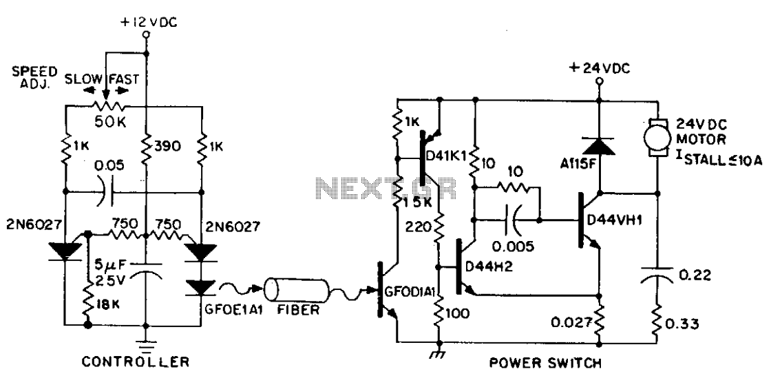
DC power can also be controlled using fiber optics. The circuit provides an insulated speed control path for a small DC actuator motor (less than Vn hp). The control logic is a self-contained module that requires approximately 300 mW...
The following diagram is for the main circuit of the motor driver. A testing version is shown near the end of this page. It is laid out differently and shows the SN7474 in logic block form and LEDs are...

This A/B Box pedal schematic for electric guitar was designed by Rick Barker. The A/B Box effect was originally intended for switching between different harmonica microphones. It features a low-noise dual preamp for improved performance. The A/B Box schematic serves...
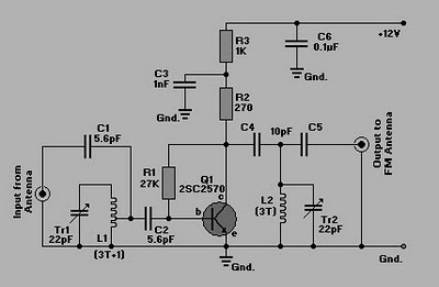
This is a simple circuit of an FM booster designed to enhance the reception of programs from distant FM stations. The amplifier effectively captures signals from far-off FM stations. The configuration is set up as a common-emitter tuned RF...
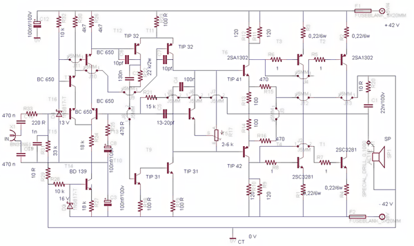
This post presents the circuit schematic diagram for a 500-watt mono power amplifier. As of July 18, 2012, the intention is to create a power sound system with a total output of 1000 watts in stereo. The design utilizes...
Pulse width modulation (PWM) is a technique to control analog circuits with a digital output. PWM is used in many applications, especially to control light intensity and speed on motors. A PWM circuit makes a square wave with a...