
Music Light Show

The described circuit serves as a sound-activated lighting system, where audio signals from a stereo or speaker output are utilized to control the illumination of light bulbs. The initial connection is made to the speaker outputs, allowing the circuit to capture the audio signal directly. An isolation transformer is employed to ensure that the circuit remains electrically isolated from the audio source, providing protection against voltage spikes and ensuring safe operation.
The audio signal is then routed through the transformer, which can help in impedance matching and signal conditioning. A 5k ohm potentiometer (pot) is integrated into the circuit to allow for manual adjustment of the volume level, enabling users to set the desired sensitivity of the circuit to the incoming audio signals.
The core functionality of the circuit lies in its ability to respond to different frequencies of sound. This is achieved through a gate circuit that utilizes a Silicon Controlled Rectifier (SCR). The SCR acts as a switch that is triggered by specific frequency ranges, which are determined by the resistor (R1, R2, R3) and capacitor combinations. Each light bulb in the circuit corresponds to a specific frequency range; when the audio signal reaches a frequency that matches the configured parameters of the gate circuit, the SCR is activated, allowing current to flow to the respective light bulb, illuminating it.
Adjusting the values of resistors R1, R2, or R3 will alter the frequency response of the gate circuit, thereby changing the audio frequency that will trigger the SCR. This feature allows for customization of the circuit to respond to different types of music or sound frequencies, enhancing the visual experience in conjunction with the audio.
The overall design emphasizes safety and adaptability, making it suitable for various applications where sound-activated lighting is desired, such as in home entertainment systems, parties, or artistic installations. Proper consideration should be given to the ratings of the components used, particularly the SCR and the light bulbs, to ensure reliable operation and prevent damage to the circuit.The circuit connects to the speaker outputs of your stereo or to the back of your speaker. The music passes through the transformer and the volume level is adjusted by the 5k ohm pot. Each light bulb is turn on by a different frequency of sound based on the resistor & capacitor combination in the gate circuit of the SCR. If the resistors R1, R2, or R3 are changed, the frequency of sound that will trigger the SCR will change.
The isolation transformer is for protection. 🔗 External reference
Related Circuits
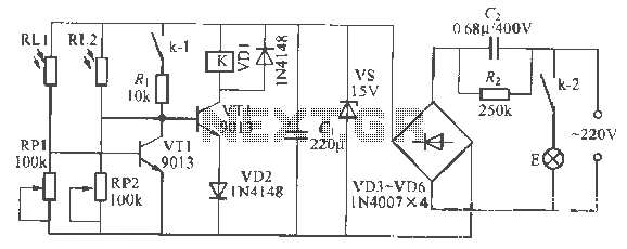
This is a remote-controlled light switch circuit that can be used for remote control toys, flashlight operation, or laser pointers. When the light from a torch illuminates the photosensitive resistor RL2, its resistance decreases, causing transistor VT2 to turn...

The following circuit illustrates a Light Activated Switch Circuit Diagram. This circuit is based on the LM311 integrated circuit, which functions as a voltage comparator. The Light Activated Switch Circuit utilizes the LM311 voltage comparator to control the switching of...
The schematic presented is a circuit for a light-activated LED utilizing an SCR (Silicon Controlled Rectifier). SCRs, which resemble transistors in appearance, operate on different principles compared to transistors. In this circuit, the SCR functions as a switching device....
This document presents the circuit diagram of an IC-controlled emergency light with a charger, which functions as a 12V to 220V AC inverter circuit. The primary features of this circuit include automatic activation of the light during mains failure...

This project page has evolved into a design discussion. Constructive suggestions and collaboration are still welcome. Please refer to the comments section. The project focuses on the development of an electronic circuit design, which has transitioned from a simple project...

The circuit can be divided into four sections: power supply, touch sensor, microcontroller, and LED driver. The touch sensor is connected to the frame. The circuit architecture consists of four primary sections, each serving a distinct function to ensure the...