
Music/Sound Controlled Disco Light

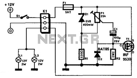
The circuit operates by utilizing the reactance of capacitor C1 to reduce the mains voltage without generating excess heat, which is a significant advantage in terms of efficiency. The capacitor's reactance effectively limits the current flow, allowing for a safe voltage reduction. Following this, the reduced AC voltage is directed to diodes D1 and D2, both of which are 1N4007 components. These diodes serve to rectify the AC voltage into a pulsating DC voltage, ensuring that the output is suitable for further processing or usage in DC applications.
The output voltage is then clamped to 24V, which is achieved through the use of additional components, likely involving a voltage regulator or zener diode in conjunction with the rectification stage. This clamping mechanism ensures that the voltage does not exceed the desired level, providing a stable output that can be utilized for powering electronic devices or circuits that require a consistent voltage supply.
In summary, this circuit effectively reduces mains voltage through capacitive reactance, rectifies it using robust diodes, and clamps the output to a safe, usable level of 24V, ensuring both efficiency and reliability in operation.The mains supply can be conveniently reduced with no heat dissipation by the reactance of C1; then rectified by D1 (1N4007) and D2 (1N4007) and clamped to 24V.. 🔗 External reference
Related Circuits
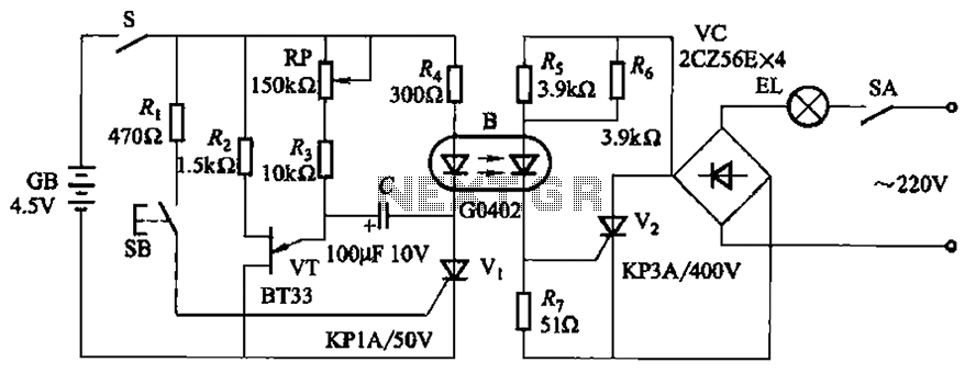
The circuit illustrated in Figure 2-48 consists of two configurations. Configuration 2-48 (a) operates using a 4.5V battery, while configuration 2-48 (b) employs AC capacitors to reduce the voltage supply. In configuration 2-48 (a), the delay time is influenced...

If R, the sensor matching resistor, is equal to the "dark" resistance of the cadmium sulfide cell, the amplifier output will range from 0 to 2 as the light level varies from "dark" to "bright." The circuit operates similarly,...

This application note discusses the use of SEPIC power modules to supply the necessary power for driving high-brightness LED arrays. These arrays serve as display backlights and necessitate a wide dimming range. The SEPIC configuration offers an efficient and...
It is assumed that most readers are considerate drivers who do not activate their rear fog lights when closely followed by other vehicles. Following drivers may mistakenly think that the vehicle is braking, leading them to react by applying...

Simple pathway lighting that provides illumination for the path at night. Extension for the solar garden light. The toroid is bifilar wound. The described circuit involves a solar-powered pathway lighting system designed to illuminate walkways during nighttime. This system...
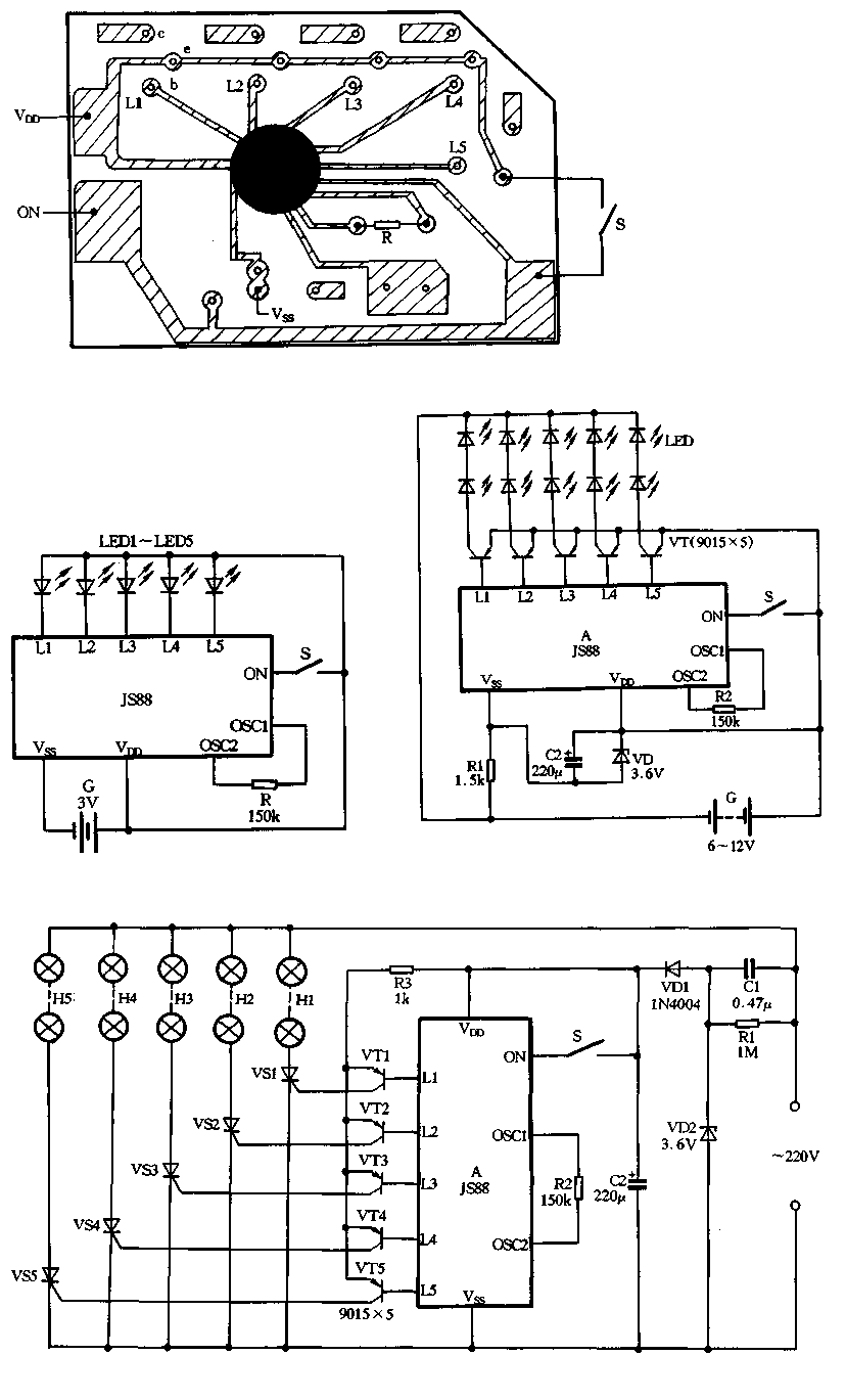
Figure 2-39 illustrates a typical application circuit for the JS88 manifold, which includes an oscillation resistor (R) that allows for fine-tuning of the water flicker frequency. When switch (S) is closed, components L1 to L5 sequentially output low signals...