
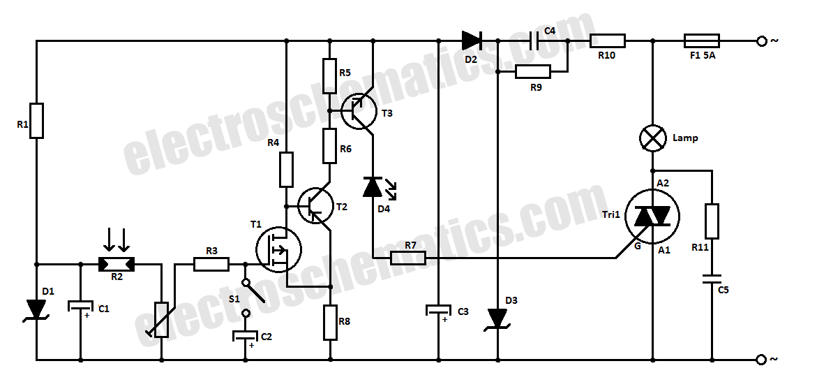
Nanoampere sensing circuit
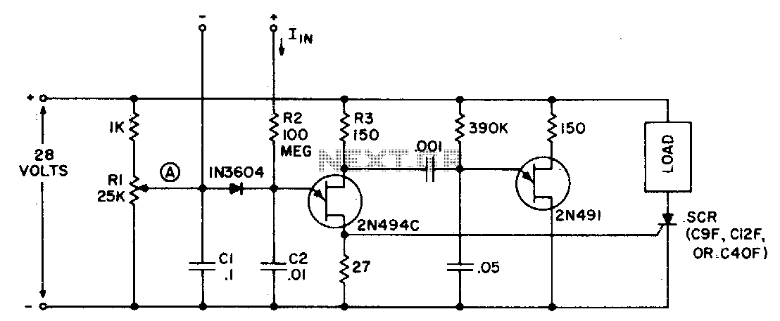
The described circuit operates effectively as a highly sensitive detection system for either current or voltage, leveraging the properties of the 2N494C transistor, which is well-regarded for its low threshold activation. The configuration of resistor Rl is critical, as it dictates the voltage at point (A), ensuring it remains slightly below the activation level of the transistor, thus allowing for precision in detection.
The input current (Iin), specified at 40 nanoamperes, is notably low, making this circuit suitable for applications where minimal current draw is essential, such as in sensor applications or low-power devices. The charging of capacitor C2 is crucial, as it serves to buffer the input signal, allowing the circuit to respond effectively to minute changes in current or voltage.
Upon activation of the 2N494C, the discharge of capacitors Cl and C2 through the 27-ohm resistor generates a sharp positive pulse. This pulse is significant as it can be utilized to trigger other components within a system, such as a controlled rectifier (SCR), which is often used in power control applications. The design ensures that the pulse generated is of sufficient amplitude to reliably activate subsequent circuitry, thereby enhancing the versatility of the circuit in various electronic applications.
Overall, this circuit exemplifies a robust design for sensitive detection applications, combining low power requirements with the ability to interface effectively with other electronic components through pulse generation.The circuit may be used as a sensitive current detector or as a voltage detector having high input impedance. Rl is set so that the voltage at point (A) is V2 to % volts below the level that fires the 2N494C. A small input current (Iin) of only 40 nanoamperes will charge C2 and raise the voltage at the emitter to the firing level
When the 2N494C fires, both capacitors, Cl and C2, are discharged through the 27 ohm resistor, which generates a positive pulse with sufficient amplitude to trigger a controlled rectifier (SCR), or other pulse sensitive circuitry. 🔗 External reference
Related Circuits
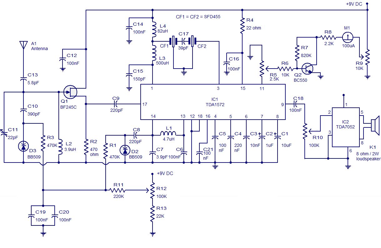
High-quality AM radio circuit based on the TDA1572 IC. The AM radio receiver circuit operates from 9V DC and has a 1W output power. It requires a minimum number of external components. The AM radio circuit utilizing the TDA1572 integrated...
The following circuit illustrates an Automatic Room Power Control Circuit Diagram. This circuit is based on the NE555 integrated circuit (IC). Features include the use of two Light Dependent Resistors (LDRs). The Automatic Room Power Control Circuit utilizes an NE555...
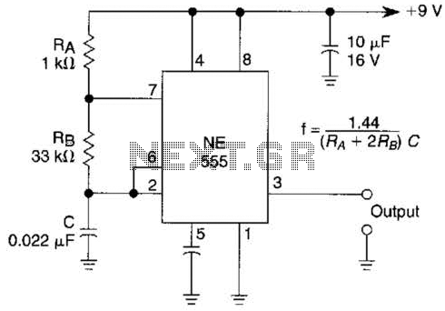
An astable multivibrator based on the 555 timer is presented. The frequency is approximately 975 Hz, determined by the values of RB and C. The astable multivibrator configuration using the 555 timer is a popular circuit for generating square wave...
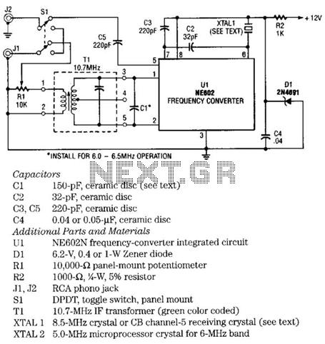
The NE602 chip, U1, contains oscillator and mixer stages. The mixer combines the oscillator signal with the input RF signal to produce signals whose frequencies are the sum and difference of the input frequencies. For example, an 8.5-MHz oscillator...
This light-sensitive automatic light switch circuit is designed to be connected to the main 220V supply. The circuit will activate a 220V lamp during nighttime. The light-sensitive automatic light switch circuit operates by utilizing a light-dependent resistor (LDR) to detect...

This is the power diagram for motor forward and reverse operation. To change the motor direction, one polarity must be altered, for example, changing R to S. For detailed information, please refer to the following. The described power diagram illustrates...
Warning: include(partials/cookie-banner.php): Failed to open stream: Permission denied in /var/www/html/nextgr/view-circuit.php on line 713
Warning: include(): Failed opening 'partials/cookie-banner.php' for inclusion (include_path='.:/usr/share/php') in /var/www/html/nextgr/view-circuit.php on line 713