
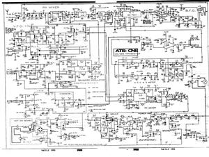
NE5532 IC For FM Stereo Radio Decoder

The NE5532 is a high-performance dual operational amplifier widely used in audio applications, including FM stereo radio decoders. The circuit typically employs the NE5532 for its low noise and high gain characteristics, making it suitable for processing the audio signals received from an FM tuner.
In the circuit design, the NE5532 is configured in a differential amplifier setup to extract the stereo audio signals from the demodulated FM waveform. The input stage of the circuit connects to the output of the FM demodulator, where the audio signals are present. The operational amplifier amplifies these signals while minimizing noise and distortion, which is crucial for maintaining audio fidelity.
Additional components in the circuit may include resistors and capacitors that set the gain of the amplifiers and filter out unwanted frequencies, ensuring that only the desired audio signals are processed. Power supply decoupling capacitors are also typically included to stabilize the power supply voltage and further reduce noise.
The output of the NE5532 feeds into a low-pass filter stage, which smooths out the audio signal, removing any high-frequency components that may remain after amplification. This filtered output can then be sent to an audio output stage, such as a speaker or headphone driver, allowing for the playback of the FM stereo audio.
Overall, the NE5532-based FM stereo radio decoder circuit is an efficient and straightforward solution for audio signal processing in radio applications, leveraging the capabilities of the NE5532 to deliver clear and high-quality sound.This circuit shows about NE5532 IC For FM Stereo Radio Decoder Circuit Diagram. Features: simple circuit, using NE5532 IC. Component: IC, .. 🔗 External reference
Related Circuits
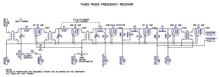
Tuned radio frequency receiver. A radio receiver consisting of several amplifier stages that... A tuned radio frequency (TRF) receiver is a type of radio receiver that utilizes multiple amplification stages to enhance the reception of radio frequency signals. The design...
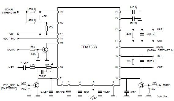
The pilot detector output is configured as an open collector output, requiring an external pull-up resistor. To set the decoder to "MONO," Pin 19 must be clamped to a voltage below 0.8V. The open collector output configuration allows for multiple...
A schematic diagram for a broadband QRP SWR metering circuit intended for use in a QRP antenna tuner. The circuit allows the user to press a momentary DPDT switch to observe an LED indicator while adjusting the capacitors of...
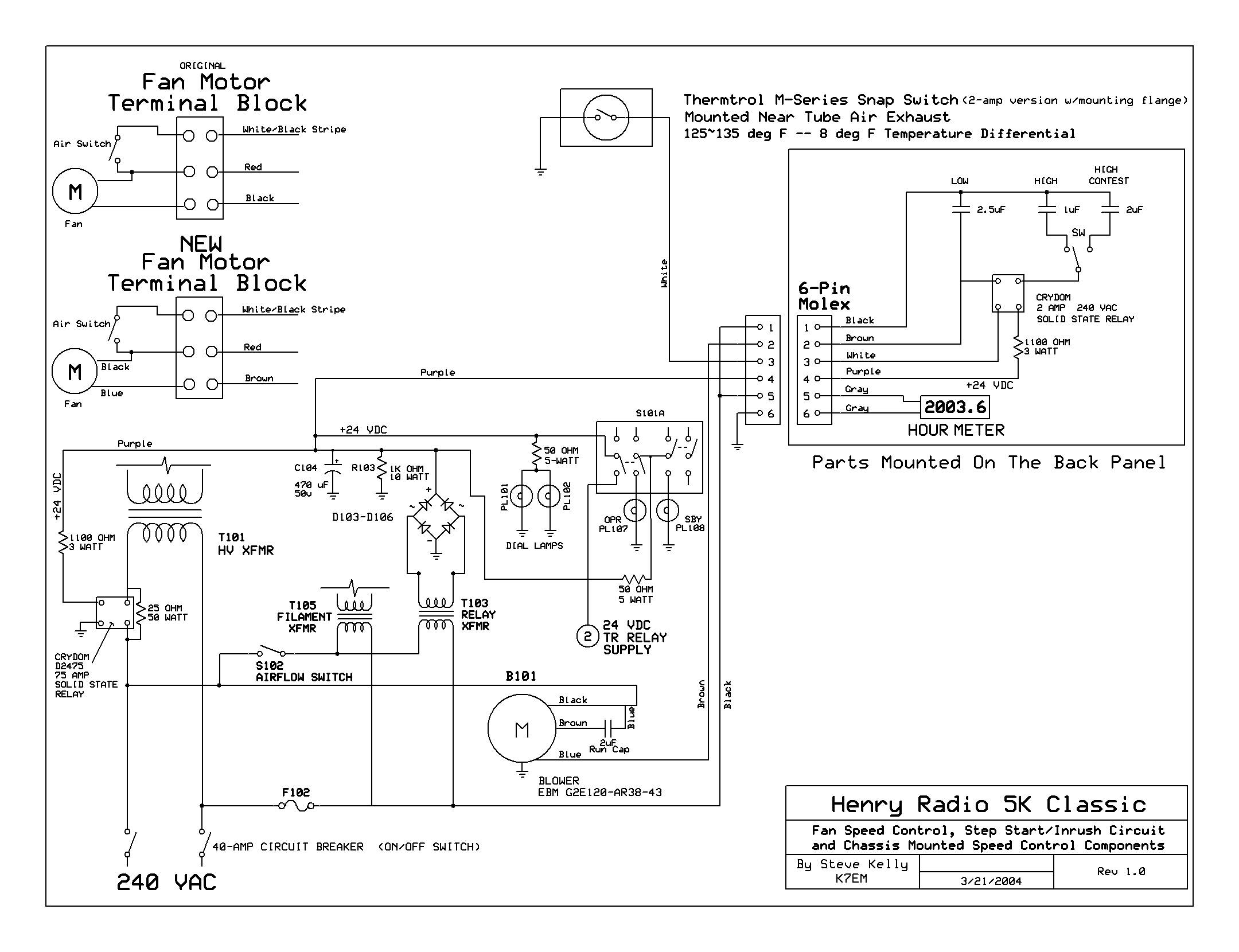
The back cover has been removed, revealing the upper deck of the power supplies and the original Dayton 2C915A blower (220VAC - 140CFM) mounted to the cabinet's underside. The RF deck enclosure has also been taken off. The upper...
This example describes the use of HS101 and HS201 radio transmitter and receiver modules to control rotating color lights, functioning as a multi-channel radio remote control device suitable for small dance floors or home use. Users positioned at any...
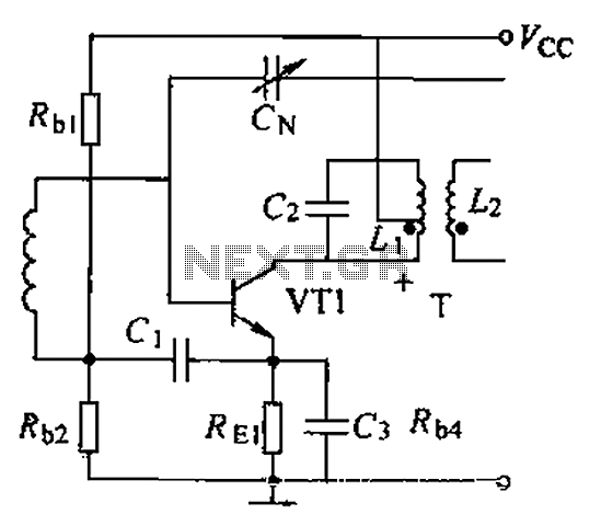
A common intermediate frequency amplifier circuit is presented, along with its components and parameters. The reference values for the components are as follows: 1) Transistors: VT1 to 3DG19, Vcc = 6V. 2) Resistance values: R1 = 50 kΩ, R2...