
tuned radio frequency receiver

A tuned radio frequency (TRF) receiver is a type of radio receiver that utilizes multiple amplification stages to enhance the reception of radio frequency signals. The design typically incorporates a series of tuned circuits, each configured to resonate at a specific frequency, allowing the receiver to selectively amplify desired signals while rejecting unwanted noise and interference.
The fundamental components of a TRF receiver include:
1. **Antenna**: The antenna captures incoming radio waves and converts them into electrical signals. It is designed to operate at the desired frequency range.
2. **Tuned Circuits**: Each amplifier stage includes a tuned circuit, which typically consists of an inductor and a capacitor. These components are arranged to form a resonant circuit that can be adjusted to the frequency of the incoming signal. This selectivity is crucial for filtering out adjacent channel interference.
3. **Amplifier Stages**: The receiver contains multiple amplifier stages, often using transistors or operational amplifiers. Each stage boosts the signal strength, ensuring that the desired signal is sufficiently amplified for further processing. The gain of each stage is carefully controlled to maintain overall stability and prevent distortion.
4. **Demodulator**: After amplification, the signal is passed to a demodulator, which extracts the audio or data information from the modulated carrier wave. Common demodulation techniques include amplitude modulation (AM) and frequency modulation (FM).
5. **Audio Output Stage**: The demodulated signal is then fed into an audio output stage, which may include additional amplification and filtering to drive speakers or headphones, providing the final audio output for the user.
The TRF receiver is known for its simplicity and effectiveness in receiving signals over a wide frequency range. However, it may be less selective than superheterodyne receivers, which use frequency mixing to achieve improved performance. Despite this, TRF receivers are often favored in applications where simplicity and low cost are paramount, making them suitable for basic radio communication and hobbyist projects.tuned-radio-frequency receiver. A radio receiver consisting of a number of amplifier stages that.. 🔗 External reference
Related Circuits
The electronic diagram of the monophonic FM receiver made with TDA7088T is shown on Pic.4.12. If built with SMD components it can be placed in a matchbox, altogether with two button-type batteries. The operating principle of this device is...
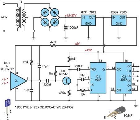
This circuit allows any infrared (IR) remote control to manage the outputs of a 4017 decade counter. It utilizes a 3-terminal IR receiver (IRD1) to capture infrared signals from the transmitter. The output from IRD1 is connected to an...
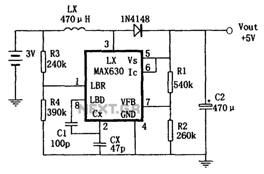
A low voltage frequency circuit utilizes the MAX630 for low battery voltage detection, functioning as an offset boost converter power supply. It is designed to maintain high efficiency (85%) while providing a DC output voltage of 5V at a...
A voltage-to-frequency converter (VFC) circuit is illustrated in the schematic diagram below. The circuit utilizes a 555 integrated circuit (IC) as the central component of its operation. The voltage-to-frequency converter (VFC) is a crucial electronic circuit that converts an input...
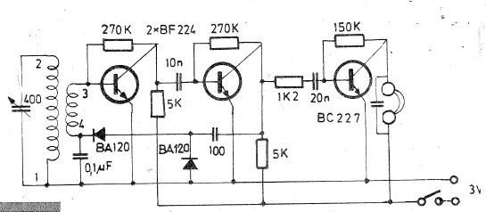
Oscillating circuits (coils) are constructed on a ferrite bar. For long wave reception, winding "1-2" consists of 135 turns, while winding "3-4" has 20 turns. For medium wave reception, winding "1-2" has 75 turns, and winding "3-4" has 7...
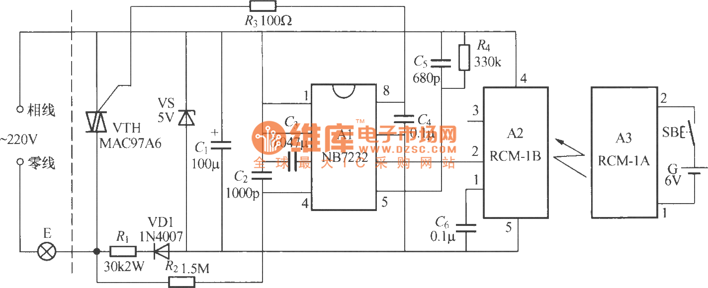
The diagram above illustrates a radio remote control dimmer circuit. This circuit utilizes a micro radio transmit/receive module in conjunction with a light modulation ASIC, resulting in a compact and easily producible design. It operates reliably and features a...