
Negative Auxiliary Voltage

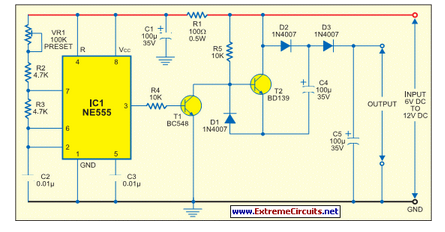
The described circuit provides a practical solution for generating a negative supply voltage from a positive voltage source without the need for bulky transformers and rectifiers. The use of CMOS technology not only ensures low power consumption but also allows for a compact design. The square-wave generator formed by the gates produces an alternating signal that is subsequently rectified by diodes D1 and D2. The rectification process converts the AC signal into a usable DC voltage, suitable for powering low-current applications.
The voltage output characteristics indicate that the negative voltage is effectively mirrored to the positive voltage, thus allowing the circuit to function in applications where a negative supply is necessary, such as in operational amplifiers or certain digital circuits. The design's flexibility is enhanced by the ability to connect an external clock signal, which can facilitate synchronization with other circuit components or systems. This feature may simplify the overall design by eliminating additional passive components, thereby reducing the total component count and improving reliability.
In summary, this circuit design is an efficient and economical approach to generating a negative voltage supply, suitable for low-current applications, while maintaining simplicity and ease of integration into existing systems.Some circuits need a negative supply voltage that only has to supply a small current. Providing a separate transformer winding for this (possibly even with a rectifier and filter capacitor) would be a rather extravagant solution. It can also be done using a few gates and several passive components. The combination of gate IC1a and the other three gates (wired in parallel) forms a square-wave generator. D1 and D2 convert the ac voltage into a dc voltage. As a CMOS IC is used here, the load on the negative output is limited to a few milliampG¨res, depending on the positive supply voltage (see chart), despite the fact that three gates are connected in parallel. However, as the figure shows, the negative voltage has almost the same magnitude as the positive input voltage, but with the opposite sign.
If a clock signal in the range of 10 50 kHz is available, it can be connected to the input of IC1a, and R1 and C1 can then be omitted. 🔗 External reference
Related Circuits
All miniature electronic devices operate off batteries. Some of them require higher than the standard battery voltages to function efficiently. Miniature electronic devices, which include a wide range of applications from portable gadgets to remote sensors, typically rely on battery...
This is a CMOS IC (CD4033) based circuit which can be used to detect presence of mains AC voltage without any electrical contact with the conductor carrying AC current/voltage. Thus it can be used to detect mains AC voltage...
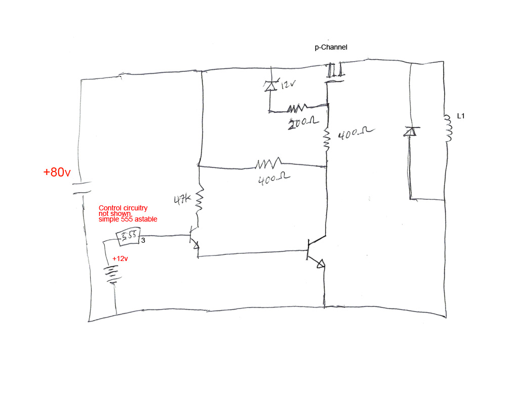
The circuit's premise involves powering an L1 coil with square pulses. A freewheeling diode is included to manage the back EMF field collapse, thereby protecting the circuitry. Previous experiments indicated that using an N-channel MOSFET on the high side...
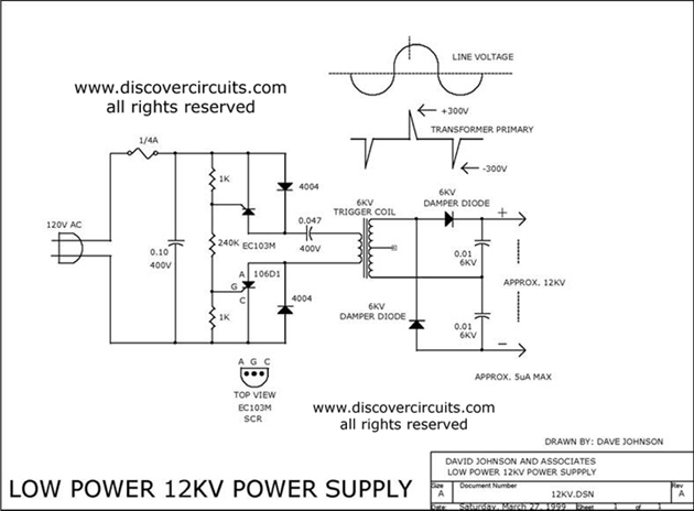
The 12kV High Voltage Generator utilizes a unique adjustment to generate approximately 12,000 volts with a current of about 5 µA. It consists of two SCRs forming two triggering circuit paths. These SCRs discharge a 0.047 µF, 400V capacitor...
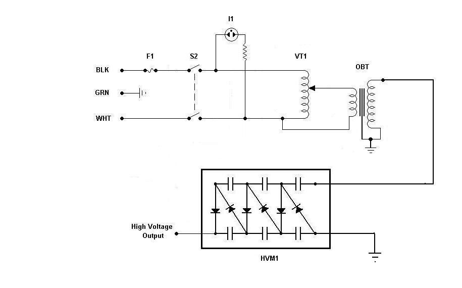
Using components from old microwave ovens, TV sets, and oil burners, it is possible to construct an economical instrument capable of producing high voltage outputs. The primary element in this setup is a voltage multiplier, which should be assembled...
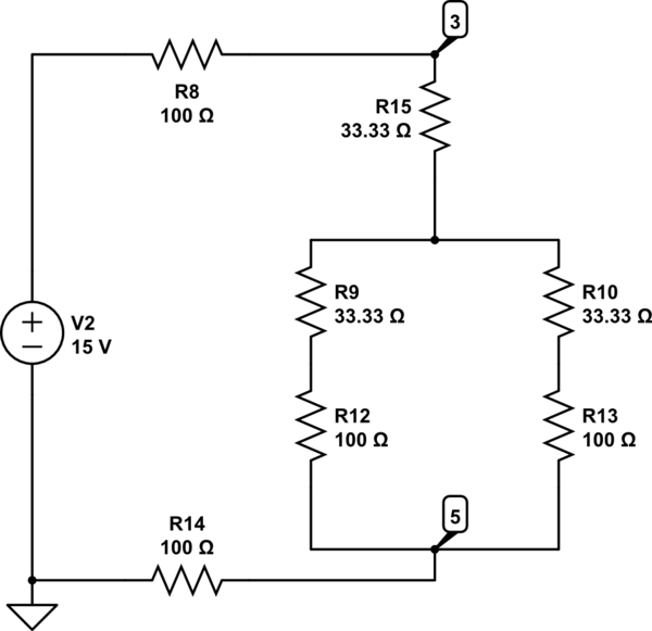
The Delta configuration of resistors R2, R3, and R4 is converted to a Wye (Y) configuration. This conversion is necessary because a voltage divider is typically employed in series circuits. The aim is to determine the total resistance in...