
Negative oxygen ion generator 1

The negative oxygen ion generator circuit is designed to produce negative ions, which can enhance air quality by neutralizing pollutants and allergens. The steady voltage power supply circuit ensures that the system operates reliably by maintaining a consistent voltage level. Diode VD1 rectifies the input voltage, while voltage regulator V1 stabilizes the output voltage, preventing fluctuations that could affect the performance of the circuit. The steady voltage diodes VS1 and VS2 are used to provide additional voltage regulation and protection against voltage spikes.
The ionization selection switch S allows the user to control the ionization process, enabling or disabling the generation of negative ions as needed. The power supply indication LED VL2 serves as a visual indicator, confirming that the circuit is powered and functioning correctly. The peripheral resistor-capacitor components work in conjunction with the aforementioned elements to filter noise and stabilize the circuit operation.
The under-voltage detection circuit plays a critical role in safeguarding the device from operating under insufficient voltage conditions. Transistors V3 and V4 are configured to monitor the voltage levels, and when the voltage drops below a predetermined threshold, steady voltage diode VS3 activates the under-voltage indication LED VL1. This LED serves as a warning signal, alerting the user to the low voltage condition that may compromise the operation of the ion generator.
The high-frequency oscillator and high-voltage generator circuit are essential for generating the necessary high voltage required for ionization. The oscillator produces a high-frequency signal that is then amplified by the high-voltage generator, enabling the circuit to create the electric field necessary for the ionization process. This combination of components ensures that the negative oxygen ions are produced efficiently and effectively, contributing to improved air quality in the surrounding environment.
Overall, this negative oxygen ion generator circuit is a comprehensive design that integrates multiple functional components to achieve its objective of generating negative ions while incorporating safety features to prevent low voltage operation.This negative oxygen ion generator circuit is composed of power supply steady voltage circuit, under voltage detection indication circuit, high frequency oscillator and high voltage generator circuit, it is shown in the figure 9-113. The power supply steady voltage circuit is made of diode VD1, power supply regulator V1, steady voltage diodes VS1,
VS2, ionization selection switch S, power supply indication LED VL2 and peripheral resistor capacitor components. The under voltage detection indication circuit consists of transistors V3, V4, steady voltage diode VS3, under voltage indication LED VL1 and peripheral resistor capacitor components.
🔗 External reference
Related Circuits
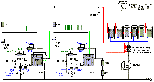
How to create a hydrogen generator using a 555 timer circuit with Pulse Width Modulation (PWM). This PWM circuit can generate hydrogen on demand. The hydrogen generator circuit utilizing a 555 timer operates by controlling the duty cycle of the...
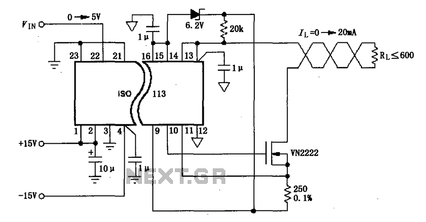
The circuit depicted in the figure consists of an ISO113 current loop isolation drive circuit that operates with an input signal (VIN) to provide an isolated amplified output of 0 to 20 mA. This current is transmitted to the...
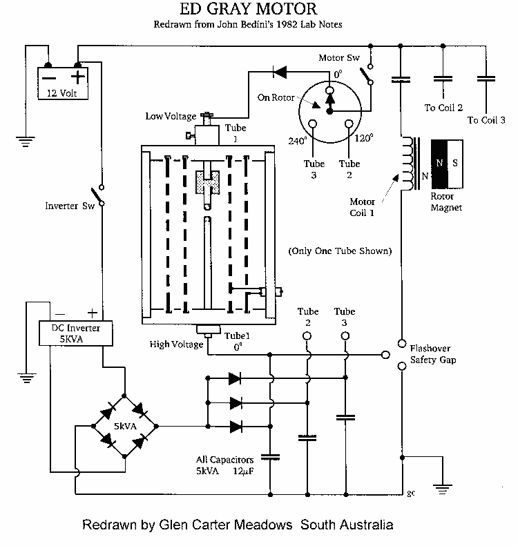
This type of design can produce a very high amperage current for a fraction of a second that can be used to do some useful work if properly harnessed. The switching device could be a rotating spark gap as...
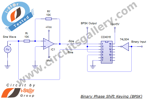
In a binary phase shift keying (BPSK) modulation scheme, the phase of a carrier signal is altered according to digital pulse signals. The BPSK modulator functions as a phase modulator, where the transmitted signal is a sinusoid with a...
A simple X-band radar detector can indicate changes in RF radiation strength at levels as low as 2 mW/cm². When radiation strikes the detector diode, it generates a voltage at the input of an amplifier. The gain of this...

A calculating resonance capacity is derived from formula (1), and an NFC Tag LSI is integrated into the antenna circuit board. The resonance frequency is measured, followed by adjustments to the resonance capacity. The circuit design involves calculating the resonance...