
Voltage Inverter II

The described circuit functions as a dual voltage power supply, capable of converting a single input voltage into both positive and negative outputs. This is particularly beneficial for applications such as operational amplifiers (op-amps), which often require dual polarity power supplies for optimal performance.
The circuit operates effectively within a range of input voltages from approximately 5V to 20V. The output voltage can be adjusted to provide a dual output ranging from ±2.5V to ±10V, making it versatile for various electronic applications.
Central to the operation of this circuit is the component U1, which is likely a voltage regulator or an op-amp configured for dual output. It is important to note that U1 dissipates around 1W of power during operation, necessitating the use of a heatsink to prevent overheating and ensure reliable performance.
Resistor R1 plays a crucial role in balancing the output voltages. Initially, R1 should be set to a mid-range value. Following this, adjustments can be made while monitoring the output voltages with a voltmeter to achieve the desired voltage levels. This process ensures that both the positive and negative outputs are equalized, which is essential for the stability of the connected load.
In summary, this circuit is an efficient and practical solution for generating dual voltage from a single supply, with considerations for thermal management and output balancing being key to its successful implementation.This simple and inexpensive circuit can produce a dual (positive and negative) voltage from a single supply input. It is therefore extremely useful for powering opamp and other circuits that require a dual voltage from a single battery.
The circuit will operate at an input voltage from around 5V to 20V and produce a output from +-2.5V to +-10V. # U1 dissipates around 1W and will therefore require a heatsink. # R1 is used to equalize the outputs. The first time you use the circuit, it should be set to mid range and then adjusted with the aid of a voltmeter. Measure each output while adjusting. 🔗 External reference
Related Circuits
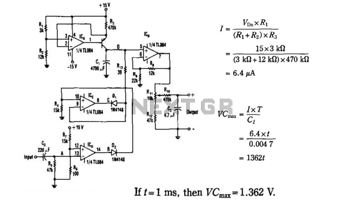
The input signal drives the ICD. Because the positive input (V+) of the ICD is slightly offset to +0.1 V, its steady-state output will be around +13 V. This voltage is sent to the ICC through D2, which sets...
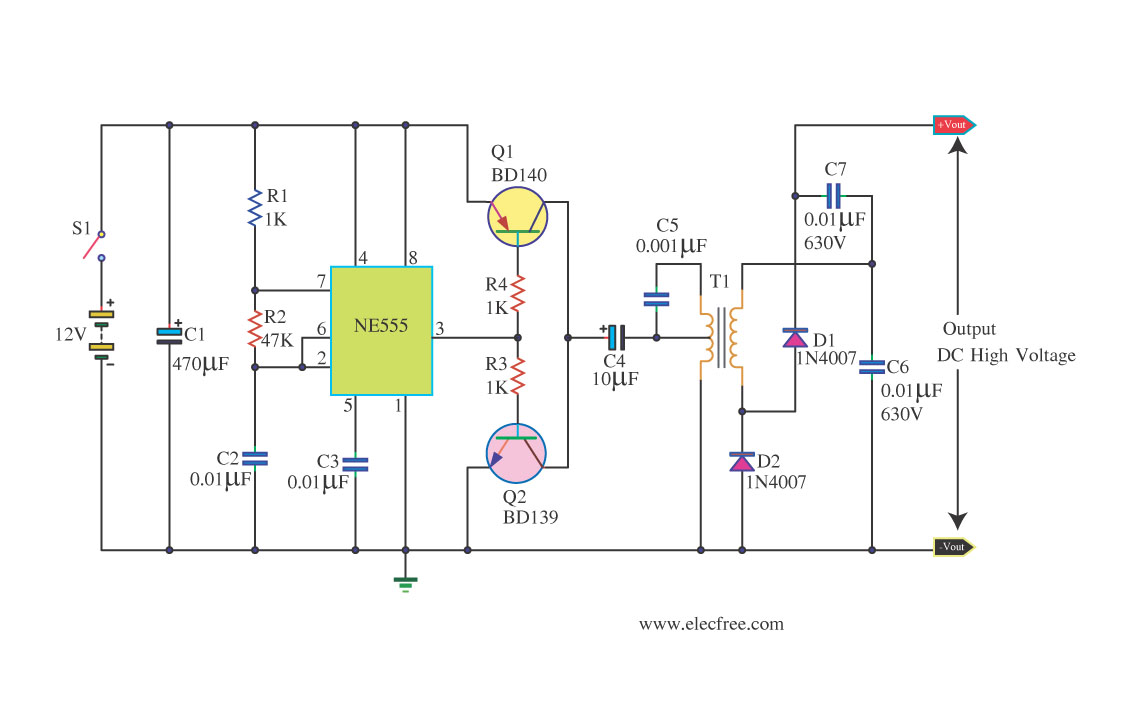
This circuit is a DC to DC inverter that can convert a 12V DC battery voltage to a high voltage of 300V DC. This circuit operates with low current. This DC to DC inverter circuit is designed to efficiently step...
This is a specialized low-voltage version of an audio preamplifier. The emitter voltage of transistor T1 is biased close to half the supply voltage (1.5V) to enable maximum output voltage swing. Both transistors are directly coupled and utilize closed-loop...
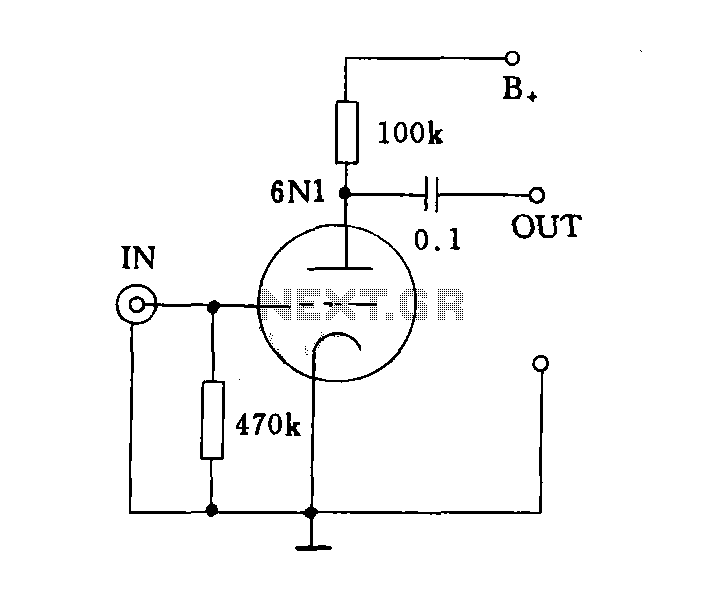
The input impedance can be classified into high-impedance and low-impedance inputs based on the requirements of various audio equipment and the load impedance. High-impedance input mode is typically utilized in general audio devices such as CD players, VCD players,...
At a T connection, the connections are clear, but at a cross, the connections are not clear, especially if there are no junction dots elsewhere in the schematic. It appears that the bottom of the I and the right...
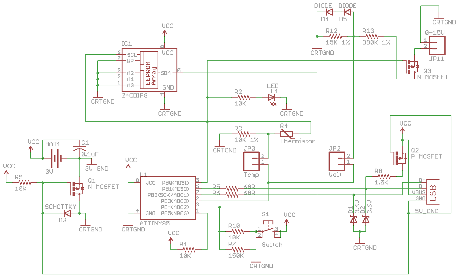
Combine the SATL and SAVL together. The schematic was updated with the voltage sensing circuit. A MOSFET was added to draw power from the voltage source only when needed. There are two jumpers, Temp and Volt, allowing the user...