
Ni-MH Ni-Cd Adjustable Constant Current Charger

The adjustable constant current battery charger circuit is engineered to cater to the specific charging requirements of Nickel-Cadmium (Ni-Cd) and Nickel-Metal Hydride (Ni-MH) batteries. The circuit typically incorporates a current source configuration that allows the user to set the desired charging current, which is crucial for optimizing battery life and performance.
Key components of the circuit may include a voltage regulator, operational amplifiers, resistors for current sensing, and a potentiometer to adjust the current output. The voltage regulator ensures that the output voltage remains stable during the charging process, while the operational amplifiers can be configured to monitor the current flow and provide feedback for maintaining the set current level.
The design should also consider safety features such as overcurrent protection and thermal management to prevent overheating during operation. Additionally, the circuit may include indicators, such as LEDs, to signal the charging status and completion.
Overall, this adjustable constant current charger circuit is a versatile solution for efficiently charging Ni-Cd and Ni-MH batteries, ensuring they operate optimally and have a prolonged lifespan.Ni-Cd Ni-MH Adjustable Constant Current Battery Charger Circuit This is a Adjustable Constant Current Ni-MH or Ni-Cd battery charger circuit. It.. 🔗 External reference
Related Circuits
After experiencing equipment failure, a decision was made to replace a combination inverter/charger unit with individual components that fulfill the same requirements. The combination unit, referred to as the "Everything Box," is an efficient solution for cost savings by...
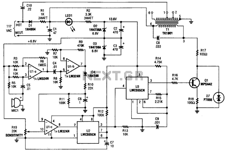
The baby-alert transmitter is constructed using an LM324 quad operational amplifier (U1), two LMC555CM CMOS oscillator/timers (U2 and U3), along with several supporting components. The transmitter activates upon detecting sound at MIC1, emitting a signal. Its operational frequency is...
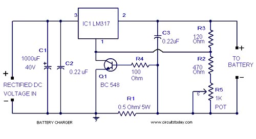
A simple lead-acid battery charger circuit with a diagram and schematic using the IC LM317, which provides the correct battery charging voltage. This lead-acid battery charger should be supplied with an input of 18 volts to the IC. The lead-acid...
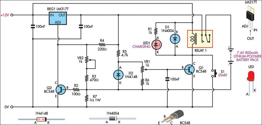
This circuit was designed to charge Lithium-Polymer cells utilized in model aircraft. Lithium-Polymer cells are significantly lighter than Ni-Cad battery packs with equivalent voltage and amp-hour ratings. However, they necessitate a strict charging and discharging protocol to maximize their...
A simple method for charging a battery from a higher voltage battery is illustrated in the circuit below on the left. Only one resistor is required to establish the desired charging current, which is determined by dividing the difference...
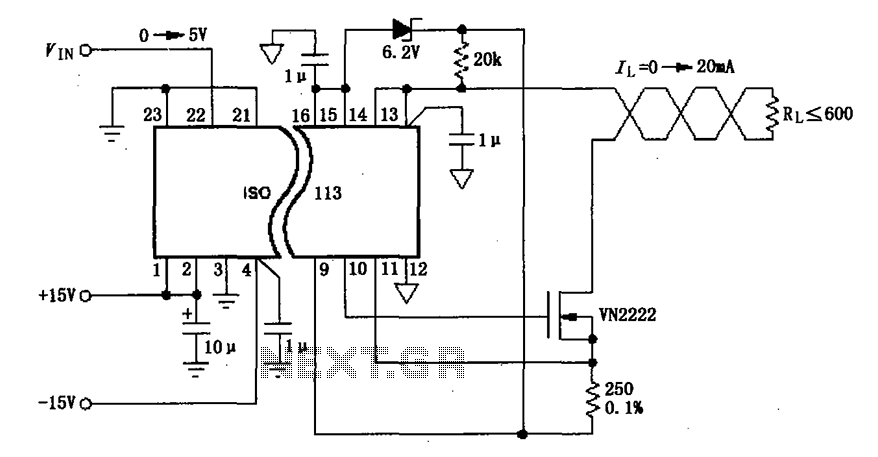
The circuit depicted in the figure consists of an ISO113 current loop isolation drive circuit that operates with an input signal (VIN) to provide an isolated amplified output of 0 to 20 mA. This current is transmitted to the...