
Ni-MH Ni-Cd Adjustable Constant Current Charger

The adjustable constant current battery charger circuit for Ni-Cd and Ni-MH batteries is a critical component in battery management systems. The circuit is designed to ensure that batteries are charged efficiently and safely, maintaining the optimal charge current to prolong battery life and prevent damage due to overcharging.
The core of the circuit typically includes a voltage regulator or an operational amplifier configured to regulate the output current. The adjustable feature allows the user to set the desired charging current based on the specifications of the battery being charged. This is commonly achieved using a variable resistor (potentiometer) in conjunction with feedback from the output current.
In addition to the current regulation, the circuit may include protection features such as thermal cutoff, reverse polarity protection, and overvoltage protection to enhance safety during the charging process. The schematic diagram usually illustrates the connections between the power source, the control circuitry, and the battery terminals.
Key components often found in such circuits include transistors or MOSFETs for switching, resistors to set the current levels, and capacitors for filtering and stability. The output current can be monitored using an ammeter or through feedback to the control circuit to ensure that the charging process remains within the desired parameters.
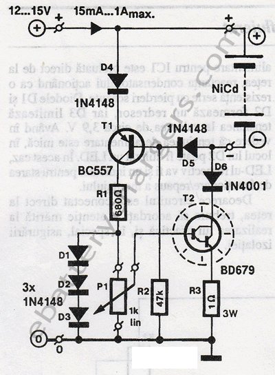
Overall, this adjustable constant current charger circuit is essential for maintaining the health and performance of Ni-Cd and Ni-MH batteries, making it suitable for various applications, including consumer electronics, power tools, and other rechargeable battery systems.Ni-Cd Ni-MH Adjustable Constant Current Battery Charger Circuit This is a Adjustable Constant Current Ni-MH or Ni-Cd battery charger circuit. It can be used to get a constant current power supply. Here is the schematic diagram of the circu.. 🔗 External reference
Related Circuits
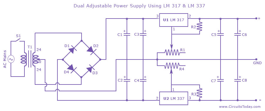
Dual adjustable power supply circuit with a diagram using IC LM317 and LM337. This variable power supply circuit has a range of 1.2 volts to 30 volts. The dual adjustable power supply circuit utilizes the LM317 and LM337 voltage regulators...
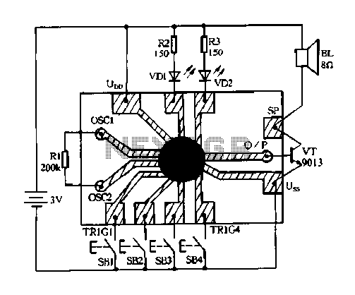
Constantly changing light and sound analog controller circuit 04 The circuit designated as the "Constantly Changing Light and Sound Analog Controller Circuit 04" is designed to modulate both light and sound outputs in a dynamic manner. This type of...
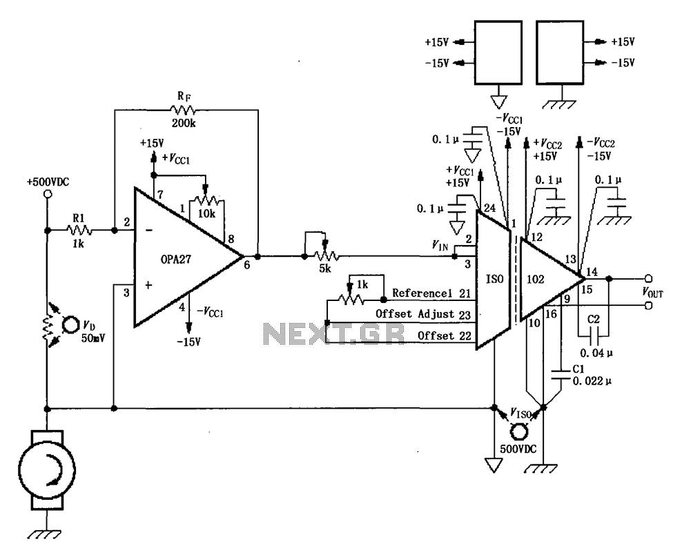
The circuit depicted in the figure consists of an ISO102 and OPA27 for measuring DC current at a voltage of +500V. It is configured between a +500V DC voltage source and a sampling resistor that is in series with...
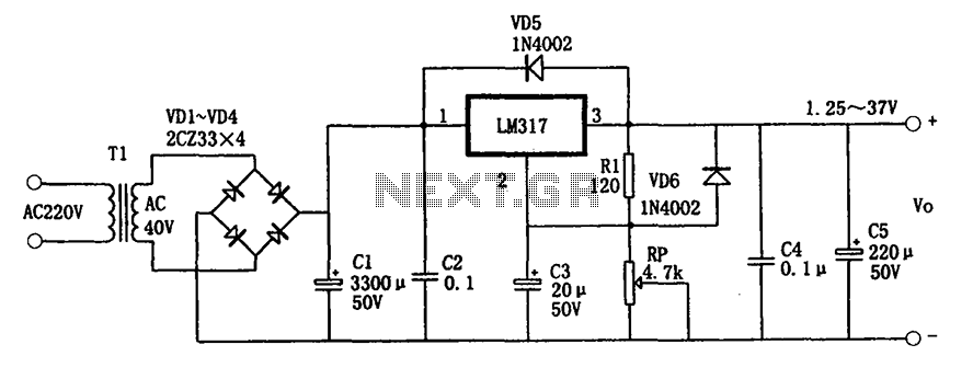
The adjustable power supply circuitry operates within a voltage range of 1.25 to 37V. It utilizes a three-terminal regulator, which is known for its good performance and stability. The compact size of the design facilitates easy installation, and it...
This circuit can be utilized as a replacement for the single current-limiting resistor typically found in inexpensive battery chargers. The alternative presented here will prove beneficial over time, as it eliminates the need to discard NiCd batteries after a...
This 24V to 36V linear battery charger is long overdue. While this is an old circuit technique, it is optimized for charging higher voltage lead-acid batteries. The 24V to 36V linear battery charger is designed to provide a stable charging...