
Constantly changing light and sound analog controller circuit 04

The circuit designated as the "Constantly Changing Light and Sound Analog Controller Circuit 04" is designed to modulate both light and sound outputs in a dynamic manner. This type of circuit typically employs various analog components such as resistors, capacitors, transistors, and operational amplifiers to achieve the desired effects.
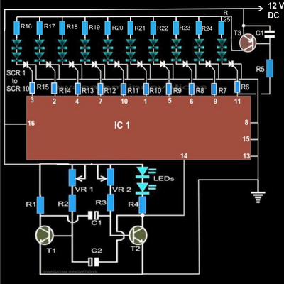
The primary function of this circuit is to create an oscillating signal that can control light-emitting diodes (LEDs) and audio outputs, generating a visually and audibly stimulating experience. The circuit may utilize a combination of astable multivibrator configurations to produce a square wave that drives the light and sound elements.
In a standard implementation, the circuit would include a power supply to provide the necessary voltage levels for the components. The oscillation frequency can be adjusted using variable resistors (potentiometers) or capacitors, allowing for customization of the light and sound effects.
LEDs can be connected in parallel or series configurations, depending on the desired brightness and color effects. The audio output can be achieved through the use of a small speaker or piezo buzzer, which is driven by the oscillating signal.
To ensure stability and reduce noise in the output signals, decoupling capacitors may be employed near the power supply connections. Additionally, filtering capacitors can be used to smooth out the output waveforms, resulting in a more pleasant auditory experience.
Overall, the Constantly Changing Light and Sound Analog Controller Circuit 04 serves as an excellent example of how analog components can be utilized to create engaging multimedia experiences through the interplay of light and sound.Constantly changing light and sound analog controller circuit 04
Related Circuits
The article explains a straightforward method for creating an incremental LED bar graph using the IC 4017, which has specifications that may not fully align with current requirements. It discusses how to modify the IC for these operations. The...
A DC-to-DC step-up converter is typically implemented using a transformer, which converts DC voltage to AC voltage, steps it up with the transformer, and then rectifies and filters the output to achieve a higher DC voltage. However, a voltage...
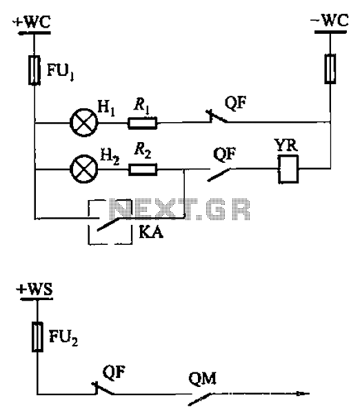
The CS2 type is a manually operated breaker mechanism commonly utilized for AC power operation and manual control signal circuits, as depicted in Figure 6-68. The circuit includes various components: wc for small signal bus control, QF for auxiliary...
In electronic technology, the triode utilizes a variety of general components and parts. The parameters of the triode and numerous electrical parametric measurement schemes are closely related to measurement results. Therefore, in electronic design, the base pin, typological judgment,...
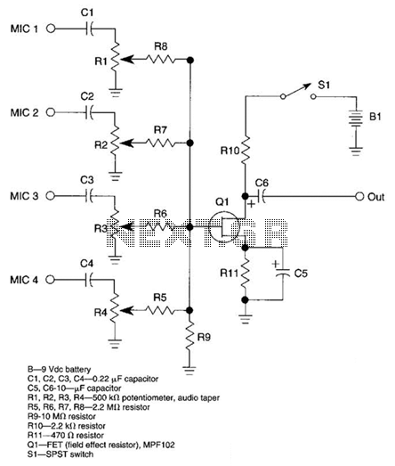
A JFET transistor is utilized as a high-to-low impedance converter and signal mixer. The input impedance is approximately 50.0 kΩ, which can be increased by adjusting resistors R5 to R8 up to 10 MΩ. The output impedance is around...
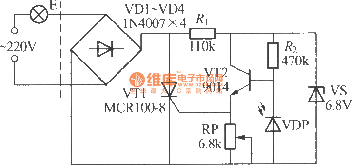
The VDP is a photodiode that exhibits low resistance during the day, approximately 1 kΩ. As a result, transistor VT2 remains off, which keeps thyristor VT1 in the off-state due to the absence of trigger current at the gate,...