
Nikon CLS Slave Flash Trigger

This project is an innovative solution for photographers seeking to enhance their lighting setup with multiple slave flashes. The slave flash system is particularly useful in scenarios requiring off-camera lighting, providing greater flexibility in flash placement and creative lighting effects. The use of an AVR microcontroller, such as the ATmega168, allows for efficient processing of the flash timing and control algorithms, ensuring reliable operation in various shooting conditions.
The implementation of the photodiode in photovoltaic mode is critical for accurately detecting incoming flashes, as it converts light into an electrical signal that the microcontroller can process. The choice of triacs for triggering the flashes provides robust performance, allowing for the control of high-voltage flash units without the need for complex relay circuits. The simple yet effective design ensures that the system can be easily assembled and modified, making it an excellent option for hobbyists and professionals alike.
The enclosure design, combining a breadboard with a professional housing, emphasizes both functionality and aesthetics. This approach not only protects the electronic components but also allows for quick adjustments and troubleshooting. The inclusion of a power regulator and the option for battery operation enhances the versatility of the system, enabling use in various environments, whether in a studio or on location.
Overall, this slave flash project exemplifies a practical application of microcontroller technology in photography, providing a cost-effective method to expand lighting capabilities and achieve more dynamic results in photographic compositions.This small project is a slave flash, which can trigger up to 4 camera flashes (non-TTL mode). It is meant for use with the Nikon CLS system, although it can probably work with other brands as well, as long as the protocol heuristics are similar. The heuristics of the Nikon CLS system are simple: there are a number of short pre-flashes, then a dela
y, then the main flash. The algorithm I am using basically waits until it sees a flash, reads in any number of flashes which occur with less than the designated time between them, and when another flash happens which is between the specified min and max times, it fires the slave flashes. The Digital Photography Tips and Technique blog wrote an article on Nikon CLS Advanced Wireless Lighting, as well as an implementation of a slave flash using the Arduino.
I used these resources heavily for understanding the protocol, although I chose to use a plain AVR instead of an Arduino for this project. The schematics are simple. I use an AVR (I am currently using an ATmega168, but in theory this should be portable to most modern AVRs with sufficient memory), with a status LED, photo diode (used in photo voltaic mode), and a few triacs for the actual trigger: The code is very simple.
I use define statements for all threshold constants and port / pin definitions. I use my own libraries for the analog readings and the time counting; I plan to release these eventually, but they are not yet on my website; please feel free to email me with questions or if you would like me to send them to you. I put the entire thing into a small enclosure, on a breadboard (I love breadboards within enclosures - it gives the professional look of a real enclosure, with the ability to change things that is inherent with breadboards!) There is a power plug and regulator in case I want to plug it into the wall; I also plan on including a small battery to power it eventually.
The LED and photo diode on are on the front, while the flash connections are on the back (I use RCA connectors for this, along with modified flashes with RCA sync inputs). 🔗 External reference
Related Circuits

This circuit will flash a string of LEDs, typically 16, with direct connection to the mains and with a period adjustable between 1 and 4 seconds depending on the setting of the 22K/1W pot. Operation at 110V should also...
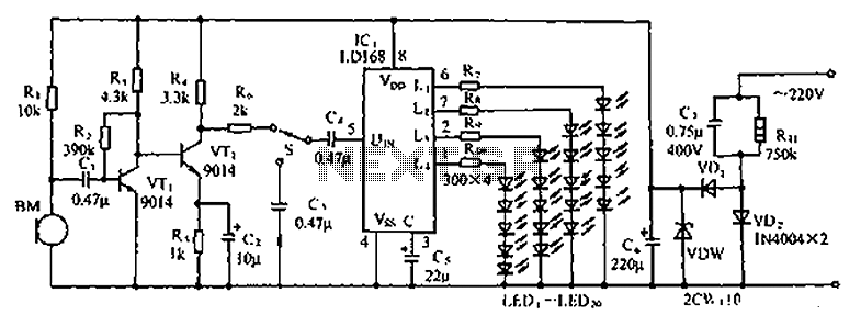
The circuit depicted in the figure involves the LD168, which functions as a sound level indicator for tape recorder speakers. It features four outputs capable of directly driving multiple light-emitting diodes. Additionally, the device can be activated by a...

An advantage of a photogate over a sound trigger is that the former activates based on the exact position of the object that interrupts the beam. For instance, the shape of a snapped elastic cord can be captured as...
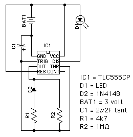
This circuit utilizes the TLC555CP timer integrated circuit to flash an LED approximately twice per second. This specific 555 timer operates on a voltage of only 3 volts, allowing it to be powered by two 1.5-volt cells. When using...
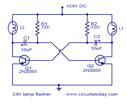
The circuit operates on 24V DC and is designed to alternately flash two 24V bulbs. It functions as an astable multivibrator with a frequency of 1Hz and a duty cycle of 50%. The lamps to be flashed are connected...
All components have been placed on the PCB, but there is uncertainty regarding the connection of the power and load in relation to the relays. The integration of relays into a printed circuit board (PCB) design requires a clear understanding...