
NMEA 2000 CAN Marine Interface

The CAN Bus (Controller Area Network) interface is a robust vehicle bus standard designed for real-time communication among microcontrollers and devices without a host computer. The asynchronous nature of the transmission allows for efficient data transfer, particularly in environments with high electrical noise, such as automotive applications.
The structure of the data frame is crucial for ensuring reliable communication. The Arbitration field is used to determine which node has the highest priority to transmit data when multiple nodes attempt to send messages simultaneously. The Control field specifies the type of data being sent, while the Data field carries the actual information, which can vary in length from 0 to 8 bytes, depending on the application requirements.
The CRC field plays a vital role in maintaining data integrity by detecting errors that may occur during transmission. The polynomial used in the CRC calculation is designed to provide a high level of error detection capability. The acknowledgment (ACK) field allows the receiving node to confirm successful receipt of the message, thereby enhancing the reliability of the communication process.
Error detection in the CAN protocol is comprehensive. At the message level, CRC checks ensure that the data has not been corrupted during transmission. Frame checks verify the integrity of the entire message format, while acknowledgment checks confirm that the intended recipient has received the data. At the bit level, Bit Monitoring ensures that the transmitted bits conform to expected values, while Bit Stuffing prevents long sequences of identical bits that could lead to synchronization issues.
Overall, the CAN Bus interface is a highly effective communication protocol that provides a reliable method for data exchange in complex systems, particularly in automotive and industrial applications. Its sophisticated error detection mechanisms and structured data frame format contribute to its widespread adoption in various electronic systems.The CAN Bus interface uses an asynchronous transmission scheme controlled by start and stop bits at the beginning and end of each character. This interface is used, employing serial binary interchange. Information is passed from transmitters to receivers in a data frame. The data frame is composed of an Arbitration field, Control field, Data field , CRC field, ACK field. The frame begins with a `Start of frame` [SOF], and ends with an `End of frame` [EOF] space. The data field may be from 0 to 8 bits. The frame check sequence is derived from a Cyclic Redundancy Code (CRC); the coefficients are generated modulo-2: X15 + X14 + X10 + X8 + X7 + X4 + X3 + 1. CAN implements five error detection mechanisms; 3 at the message level and 2 at the bit level [Also incorporates error flags].
At the message level: Cyclic Redundancy Checks (CRC), Frame Checks, Acknowledgment Error Checks. At the bit level: Bit Monitoring, Bit Stuffing. 🔗 External reference
Related Circuits
A method for measuring static electricity for a science project was sought. An old copy of "Getting Started in Electronics" by Forrest M. Mims III was referenced for guidance. To create a static electricity measurement circuit, a simple design can...
A habit-acquisition system that tags physical objects, such as dumbbells and medicine bottles, with RF tags or microcontrollers to detect and log user interactions with these items. It includes virtual plants and creatures that simulate the health of real-world...
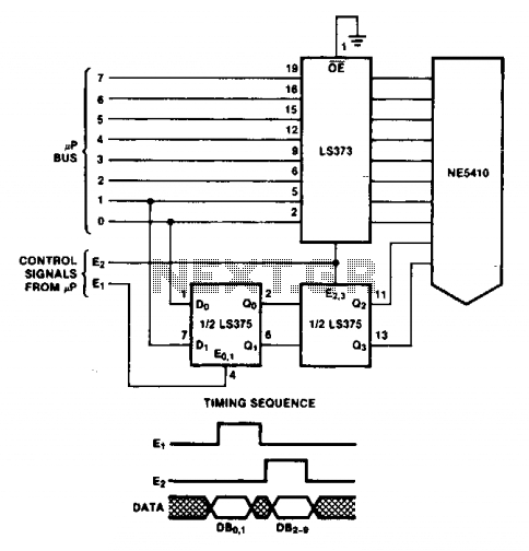
The double latch technique ensures that valid data is latched to the Digital-to-Analog Converter (DAC) until it is updated by the E2 pulse. The timing of this process will depend on the specific processor utilized. The double latch technique is...
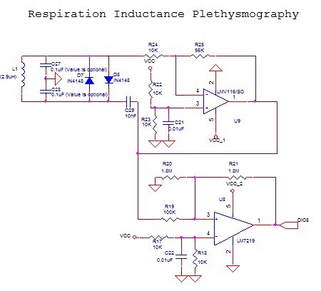
The LMV116 is an enhanced slew rate version of the LMH6645. The high-speed LMH devices are very sensitive to output capacitance (typically designed to drive back-terminated loads) and can begin to oscillate with direct capacitive loads as low as...
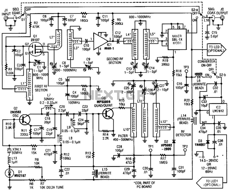
This converter allows the reception of frequencies ranging from 800 to 1000 MHz on any scanner that operates within the 400 to 500 MHz range. The converter can be configured to cover either the 800 to 900 MHz band...
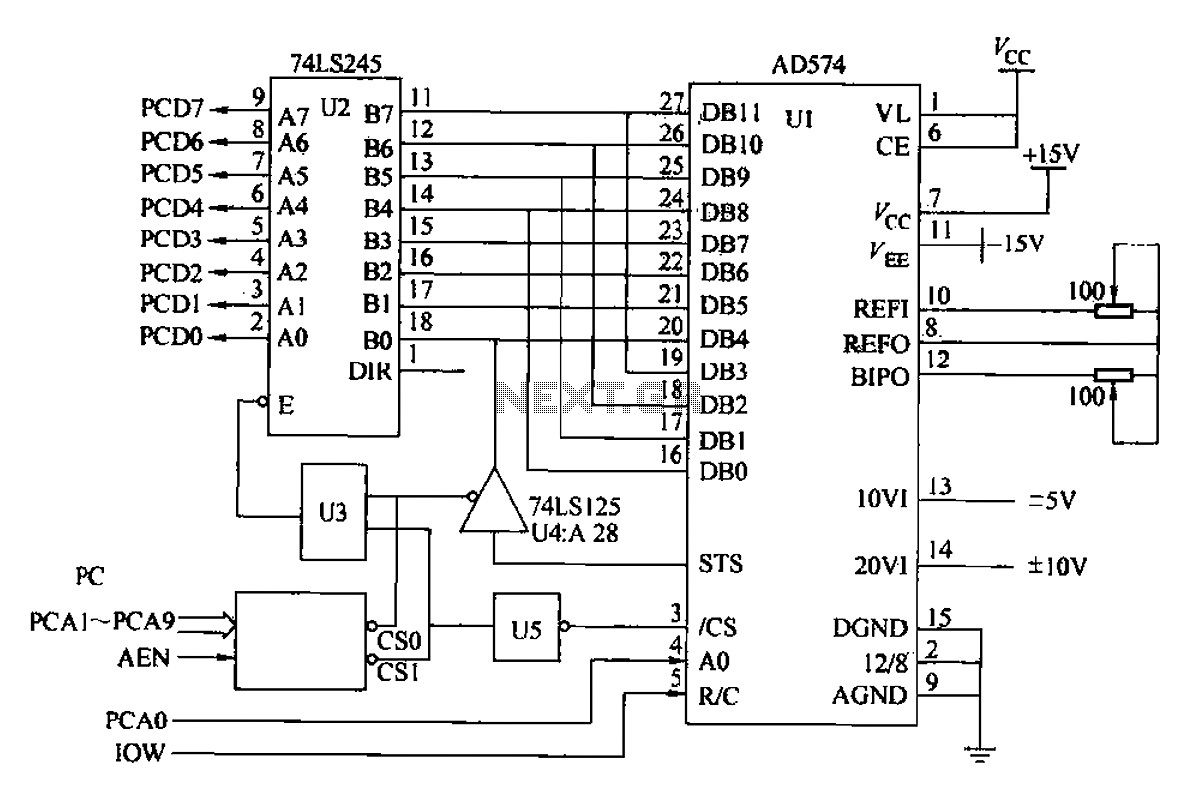
Another example is provided using the AD574 and PC bus. The AD574 converter is represented by U1, while U2 is a 74LS245 bidirectional data buffer. U3 is a 74LS00 two-input AND gate, U4 is a 74LS125 tri-state output gate,...