
Noisy Pot-like noise in preamp circuit

The preamp circuit in question is crucial for amplifying low-level audio signals before they are sent to the power amplifier stage in a powered subwoofer system. When issues arise, such as static or popping noises, it is important to systematically diagnose the problem.
Potential causes for these noises may include poor connections, faulty components, or interference from external sources. Inspecting the circuit for loose or corroded connections is essential; these can introduce noise into the signal path. Additionally, checking capacitors for signs of wear or leakage is advisable, as degraded capacitors can lead to unwanted noise.
Another consideration is the power supply. Variations in voltage or ground loops can introduce noise into the audio signal. Ensuring that the power supply is stable and that proper grounding techniques are employed can help mitigate these issues.
Furthermore, shielding of the circuit may need to be evaluated. If the preamp circuit is exposed to electromagnetic interference from nearby devices, it may pick up unwanted noise. Implementing proper shielding techniques or relocating the circuit away from interference sources can improve performance.
Finally, testing the circuit with an oscilloscope can help visualize the noise and identify its source. By analyzing the waveform, it is possible to determine whether the noise is occurring at the input stage or if it is being introduced later in the signal chain.
In summary, addressing static or popping noises in a preamp circuit requires a thorough examination of connections, components, power supply stability, grounding, shielding, and signal analysis.Hi there, I have a preamp circuit that is part of a powered subwoofer that is making a static/popping noise. It sounds similar to the scratchy, dirty.. 🔗 External reference
Related Circuits
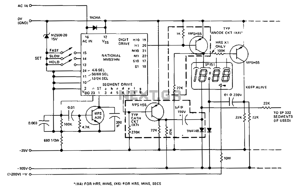
A CMOS clock circuit is capable of driving a multi-digit gas discharge display. This simple circuit does not include an alarm feature but allows for a flashing colon to indicate morning and afternoon. The circuit requires seven drive circuits...
This is a simple function generator built around a single 8038 waveform generator IC. The circuit is capable of producing sine, square, or triangle waves within a frequency range of 20Hz to 200kHz. The function generator circuit utilizes the 8038...
The circuit on this page is for a simple light detector circuit board that has 8 detectors that can be used with visible or infrared light systems. The detectors use LM339 voltage comparators as the active element. Phototransistors or...
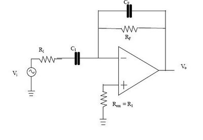
The differentiator circuit is an application circuit derived from mathematical principles influenced by capacitor behavior. The circuit, as illustrated in the accompanying image, is a simple differentiator configuration. To derive the differentiator formula, the following sequence is used: Ic...
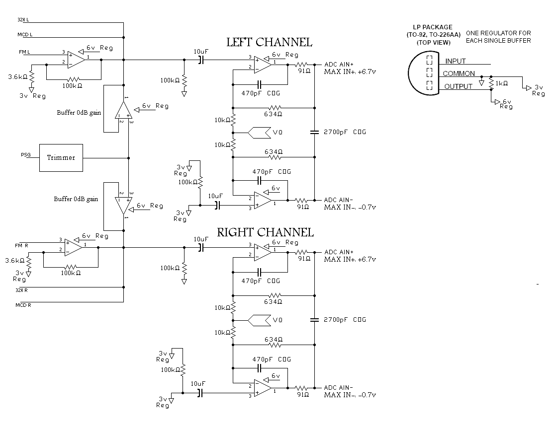
A program is needed to set the channels to their maximum level or to write the full scale to the Digital-to-Analog Converter (DAC). The MD schematics indicate that the audio signals are mixed with ratios of 0.0431 for the...
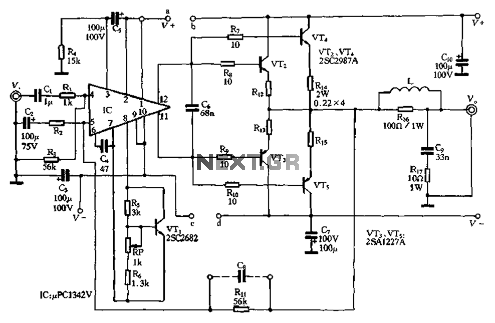
The pLPC1342V and NE are two companies involved in a tube amplifier circuit utilizing 2SA1227A and 2SC2987A transistors, achieving a maximum output power of up to 120W with a cutoff frequency of up to 500 MHz. The circuit, illustrated...