
Non-diode rectifier

In the context of electronic circuit design, the use of a single-supply operational amplifier (op-amp) in a bipolar signal environment presents unique challenges. The op-amp is typically designed to operate with dual power supplies, which allows for a more straightforward handling of both positive and negative signal swings. However, when constrained to a single supply, the design must adapt to accommodate the bipolar nature of the input signals.
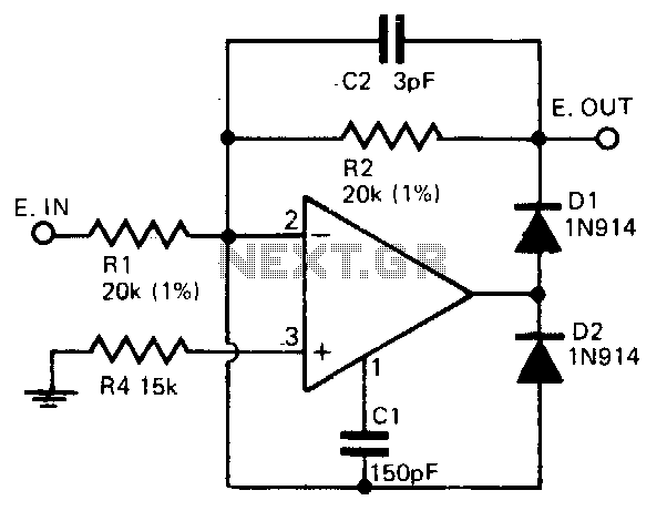
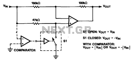
The proposed circuit (A) demonstrates a solution to this problem by utilizing a high-precision full-wave rectifier configuration. This approach eliminates the need for diodes, which are commonly used in traditional rectifier designs. Diodes introduce forward voltage drops and can limit the frequency response of the circuit. By employing an op-amp in the rectification process, the circuit achieves improved accuracy and a wider bandwidth.
The full-wave rectifier circuit operates by taking advantage of the op-amp's ability to amplify and invert signals. The feedback network around the op-amp is configured to ensure that both halves of the input waveform are utilized effectively. This results in a rectified output that closely follows the input signal's envelope, providing a high-fidelity representation of the original waveform.
Moreover, the high-frequency limit of the op-amp plays a crucial role in determining the performance of the rectifier. The selected op-amp must have a sufficient gain-bandwidth product to handle the frequencies of interest without significant distortion. The design may also include additional passive components, such as resistors and capacitors, to fine-tune the response and stability of the circuit.
In summary, the circuit in (A) exemplifies a sophisticated approach to rectification using a single-supply op-amp in a bipolar signal environment. By eliminating diodes and leveraging the op-amp's capabilities, the design achieves high precision and an extended frequency response, making it suitable for various applications where accurate signal processing is required. As we all know, when a single-supply op amp, a bipolar signal environment to achieve a simple function may be difficult. Sometimes the need for additional operational amplifier s and other electronic components. Think about it, this pattern is there any advantage The answer lies in the simple circuit in (A). Do not need diodes, this circuit is a high-precision full-wave rectifier, the rectifier is equal to the op amp itself with high-frequency limit.
Related Circuits
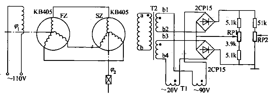
The transmitter (FZ) winding and receiver (SZ) correspond to the three-phase windings connected to a 110V AC voltage supply for transmission. The field winding, early start angle, and receiver output voltage at both ends of the stator windings reflect...
A precision half-wave rectifier utilizing an operational amplifier will achieve a rectification accuracy of 1% from DC to 100 kHz. A precision half-wave rectifier circuit is designed to convert an AC signal into a unidirectional output while maintaining high accuracy...
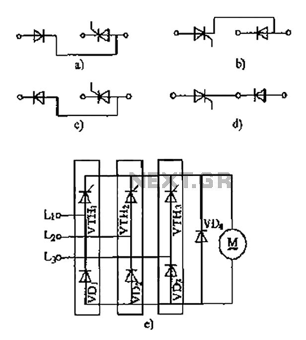
The thyristor linking arm rectifier module is a three-phase half-controlled bridge rectifier circuit. The thyristor-rectifier module linking arm consists of a thyristor and a rectifier diode connected in series or parallel, designed to fulfill specific requirements in power circuits....
PWM rectifier power controller power supply. Visit the page to read the explanation about the associated circuit diagram. A PWM (Pulse Width Modulation) rectifier power controller is a sophisticated electronic circuit designed to convert alternating current (AC) to direct current...
The operational amplifier (op amp) can function as either an inverter or a buffer, depending on the polarity controlled by a switch. When configured as a buffer, the gain remains constant at 1. In contrast, when functioning as an...
This circuit utilizes a 555 timer configured to operate in astable mode. This setup generates a continuous output through Pin 3 in the form of a square wave. When the timer's output transitions to a high state, it triggers...