
Xenon Strobe Light

The circuit described operates at a high DC voltage, specifically around 340V, which poses significant risks due to the potential for lethal electrical shock. The lack of isolation from the mains power supply exacerbates this danger, as there are no transformers or isolation barriers to protect the user from high voltage. It is crucial to ensure that all capacitors are discharged before any maintenance or adjustments are made to the circuit, as they can retain dangerous levels of charge even after the power has been turned off.
The primary component in this circuit is a xenon flash tube, which functions as a triggered gas discharge device. The tube remains non-conductive until a high voltage, typically between 3 to 5kV, is applied to ionize the xenon gas within it. This ionization process transforms the gas into a low impedance state, allowing current to flow through the tube and producing a brief but intense flash of light.
The circuit may include components such as a high-voltage power supply, a triggering mechanism (often a capacitor that is charged to the required voltage), and protection elements to safeguard against overvoltage or current surges. It is essential to design the circuit with appropriate safety measures, such as using high-voltage rated components and ensuring that the layout minimizes the risk of accidental contact with live parts.
When working with such high-voltage circuits, it is imperative to follow strict safety protocols, including the use of insulated tools, wearing appropriate personal protective equipment, and ensuring that the work area is free from conductive materials that could inadvertently create a path for electrical current.Since the circuit operates at greater than mains potential and is not isolated by a transformer, it is extremely dangerous. The DC operating potential is about 340V, and there is more than enough stored charge to kill you many times over (although in my experience, once is usually sufficient).
This is not meant to be funny - this is truly serious stuff. In addition, the circuitry usually is directly mains (line) powered, with no isolation. Discharge all capacitors before working on any flash system. A xenon flash tube is a triggered gas discharge device. A voltage may be impressed across the tube and it will not conduct until the xenon gas is ionised by an external high voltage (typically 3 to 5kV). Once triggered, the gas becomes a very low impedanc 🔗 External reference
Related Circuits
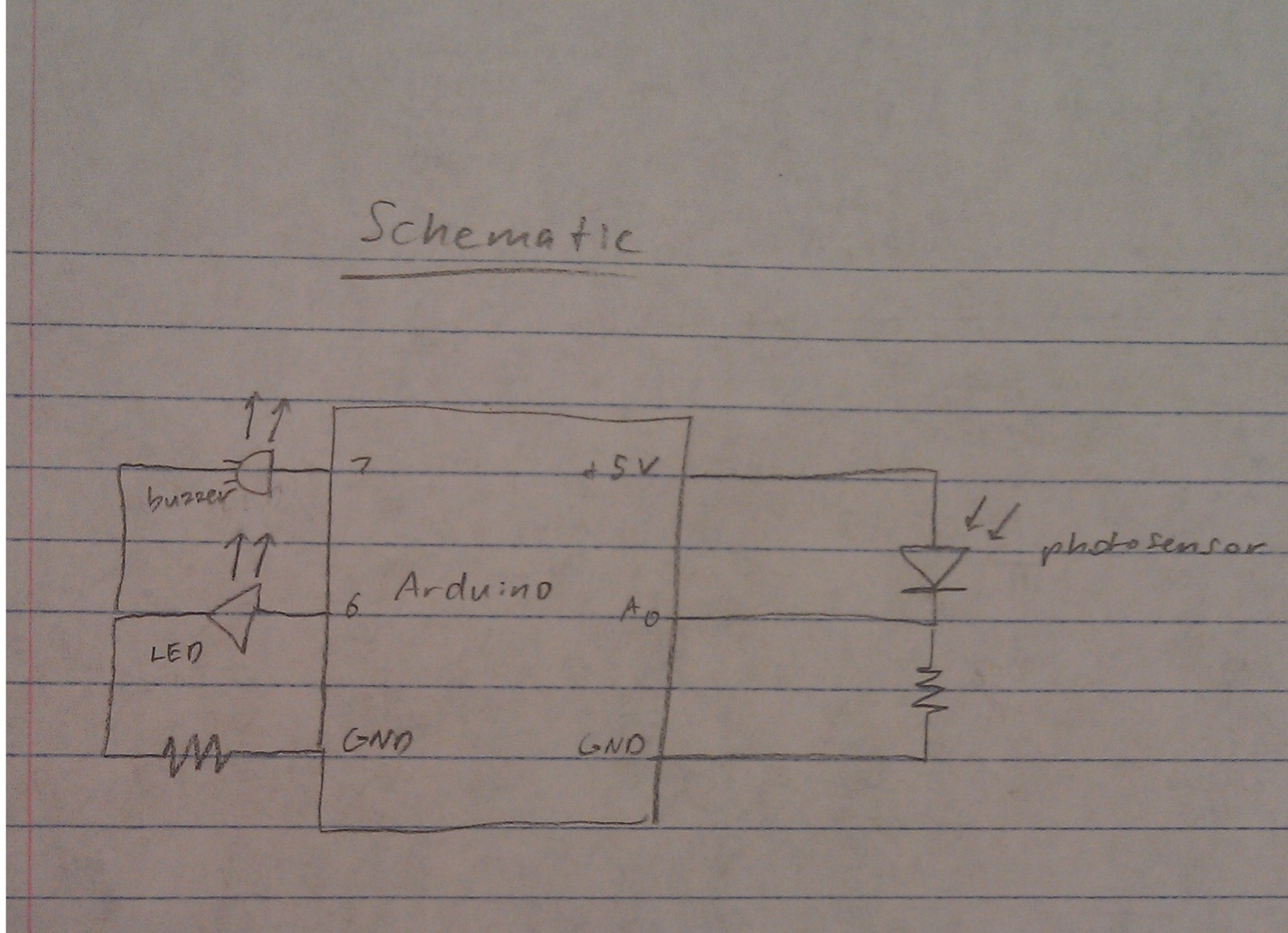
A nightlight combined with a wake-up alarm has been developed. This nightlight incorporates six LEDs that activate when a photosensor detects low ambient light levels. Additionally, a buzzer plays a cheerful tune when ambient light levels increase again. The...

Switch S1 allows for direction change (Up/Down), Pot1 adjusts the clock speed, and LED D1 serves as an indicator for the clock speed. The circuit utilizes a switch (S1) to control the direction of operation, allowing for two modes: upward...
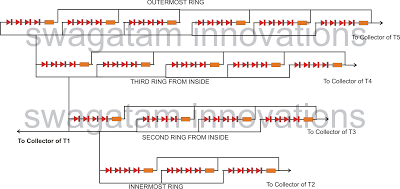
The following article outlines a sophisticated LED sequencing and diverging ring light that can serve as a tail brake light in vehicles. This circuit concept was proposed by a dedicated reader, Mr. Bobby. The design aims to create a...
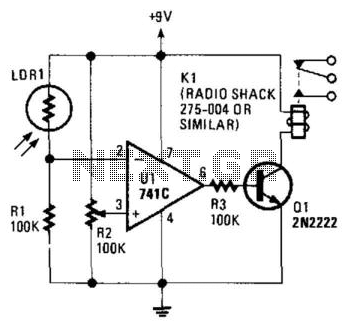
The circuit's threshold is determined by resistor R2. When the intensity of light on the LDR decreases, the resistance of the LDR increases, resulting in a lower voltage at the inverting input of the 741 operational amplifier. The reference...
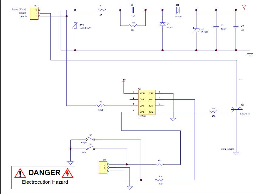
Assistance is required to modify a light dimmer circuit connected to a PIC12C508 microcontroller. This circuit is designed for the... The light dimmer circuit utilizing the PIC12C508 microcontroller serves to control the brightness of a light source through pulse width...

This light-dependent sensor utilizes light-dependent resistors (LDRs) to detect the presence or absence of light. The alarm remains inactive as long as the light source illuminating the LDRs is constant. However, if the light is interrupted, the alarm is activated. The...