
Novel delay lighting switch circuit

The described circuit utilizes a switch (S) to control the charging and discharging of a capacitor (C) in conjunction with a silicon-controlled rectifier (SCR) and diodes (VDI and VD2) to manage the flow of alternating current (AC) to a lamp (H). When the switch S is closed, the positive half-cycle of the AC voltage is directed through diode VDI and resistor R, allowing the capacitor C to charge. The SCR, once triggered, allows current to pass through to the lamp H, illuminating it during the positive half-cycle.
During the negative half-cycle, diode VD2 conducts, providing an alternative path for current to flow to the lamp H, ensuring that it remains powered. This dual-path operation allows the lamp to receive continuous power, even as the AC cycle alternates. When the switch S is opened, the capacitor C begins to discharge through the resistor R. The SCR remains conductive due to the discharge current, which sustains the light output from the lamp H. However, the interruption of the negative half-cycle by opening switch S leads to a reduction in the effective voltage across the lamp, causing it to dim.
The circuit's operation is dependent on the timing of the capacitor's discharge and the characteristics of the SCR, which requires a gate trigger current to remain conductive. As the capacitor discharges, the gate current diminishes until it reaches a threshold where the SCR can no longer sustain conduction. This occurs at the zero crossing of the AC voltage, resulting in the lamp H turning off.
This configuration is useful in applications where a controlled dimming effect is desired, allowing for gradual illumination and extinguishing of the lamp, enhancing user experience while managing power effectively. The design can be implemented in various lighting applications, providing both functionality and efficiency in AC-powered lighting systems.Closing the switch S, AC positive half cycle through VDI, R vs SCR opened simultaneously at both ends of the capacitor C is full charge. In this case the positive half cycle alternating current through the lamp H vs power, negative half-cycle through the
diode VD2 to the bulb H power, so in this case the lamp H total pressure supply. When you turn off the lights, turn on the switch S, the capacitor C discharges through the resistor R, the discharge current is maintained vs SCR continues to conduct, so light bulbs H in the positive half cycle of the current through the still, but because S cut off the negative half cycle of the power supply VD2 loop, so the lamp H in a semi-state voltage power supply, lamp dark light. About 1 minute after the capacitor C is discharged, the loss vs SCR gate trigger current at the zero crossing of the AC off, the lamp goes out.
Related Circuits
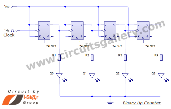
This document discusses an Asynchronous 4-Bit Binary Up Counter, a circuit constructed from several J-K flip-flops connected in a cascade configuration to produce a four-bit counting sequence. An up counter is a digital counting circuit that increments its count...

This circuit represents an FM transmitter, also referred to as an FM Bug, which consists of 18 essential components for optimal functionality. The circuit begins with an electret microphone on the far left side, and the signal flows electrically...
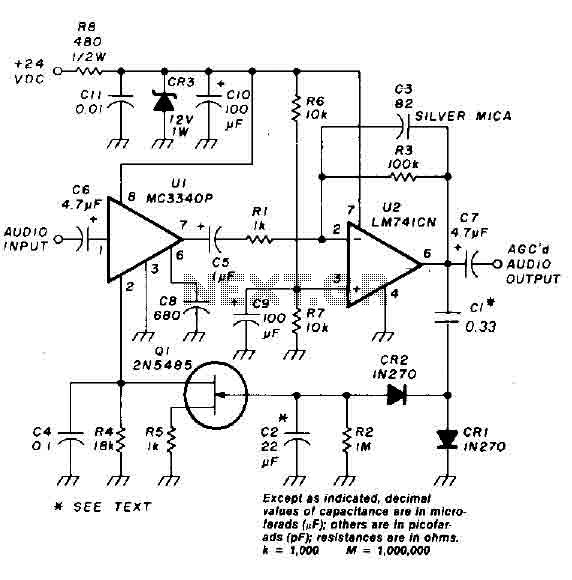
An audio signal applied to the input VI is passed through the operational amplifier 741, designated as U2. After amplification, the output signal V2 is sampled and sent to a negative voltage doubler/rectifier circuit composed of diodes CR1 and...
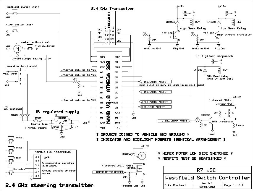
The core of the switch controller is an Arduino Nano microcontroller, which will serve as the interface between the dashboard switches, wireless steering wheel buttons, and the vehicle's lighting, indicators, windscreen wipers, and DigiDash2 GPS stopwatch. This setup facilitates...
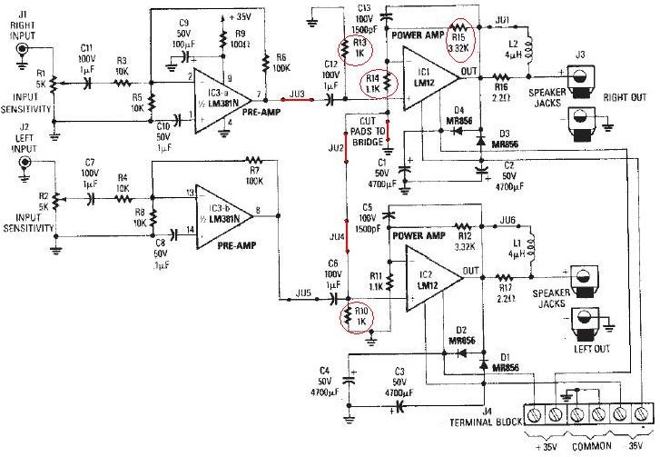
The LM12 audio amplifier circuit is designed to deliver high output power for loads with impedances of 4 ohms or 8 ohms. The maximum output power achievable by this amplifier is approximately 60 watts for a 4-ohm load and...
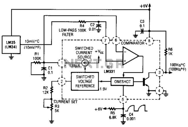
In this circuit, an LM34 or LM35 generates a frequency that is proportional to temperature. The reference current (138) is established through resistor R3. The output can be utilized to drive a display, frequency counter, or other indicating devices...