
NTC phase asynchronous motor protection circuit

The semiconductor thermistor serves as a critical component in thermal protection systems, particularly in electrical applications where monitoring and managing temperature is essential for operational safety and efficiency. The thermistor's sensitivity to temperature changes allows it to provide real-time feedback on the thermal state of the winding, which is crucial in preventing overheating and potential damage to the motor or other electrical components.
In a typical configuration, the thermistor is strategically placed near the three-phase stator windings to ensure accurate temperature readings. The use of epoxy cement not only secures the thermistor in place but also provides additional insulation and protection against environmental factors. The choice between NTC and PTC thermistors depends on the specific application requirements; NTC thermistors are generally used for applications requiring a decrease in resistance with increasing temperature, while PTC thermistors are used where an increase in resistance is desirable as temperatures rise.
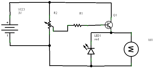
The circuit design, as indicated in Figure 4-1, incorporates a switch circuit based on a single tube amplifier, which is essential for amplifying the signal from the thermistor. This amplification is necessary for effective temperature monitoring and control, ensuring that the system can react promptly to any changes in temperature. The selection of the appropriate thermistor type, such as RRC6 or MF-15, is critical, as it affects the accuracy and responsiveness of the temperature measurements. The specified resistance values at different temperatures provide insight into the thermistor's behavior and its suitability for the intended application.
Overall, the integration of a semiconductor thermistor in a thermal protection circuit enhances the reliability and safety of electrical systems, making it a vital component in modern electronic designs.Semiconductor thermistor embedded thermal protection element belongs, it is sensitive to temperature, temperature error of 5. Its reliability, small size (diameter 3. Smm), easy to install, easy to embed winding, use it as a temperature sensing element can effectively reflect the electrical winding temperatures motivation. Thermistor on the three-phase stator windings, close to the wire, with epoxy cement. Thermal resistance has a negative temperature coefficient thermistor (NTC) and positive temperature coefficient thermistor (PTC) of the points. Circuit shown in Figure 4-1. Wherein Figure 4-1 (b), (c) only one shown protection circuits, the main circuit not shown. They are a switch circuit consisting of a single tube amplifier. Thermistor brother., R. ., R., The choice RRC6 type or MF-15 type (lokfl, 20 ), this thermistor in about lkfl 100 when, 110 at about 0.6k, Cl.
Related Circuits
In a prior post titled "Timing is Everything," the application of PWM (Pulse Width Modulation) signals for controlling devices such as LEDs was discussed. This technique is particularly beneficial when working with digital devices, including microchips and microcontrollers, which...
An ultrasonic cleaner is effective for cleaning specific items. This circuit employs a microcontroller to manage timing and provide a digital display, although a basic oscillator can be utilized if preferred. RESL and RES2 are piezoelectric transducers activated by...
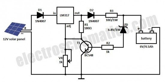
This is a solar charger circuit designed to charge Lead Acid or Ni-Cd batteries using solar energy. The circuit captures solar energy to charge the batteries. The solar charger circuit typically consists of several key components, including a solar panel,...
The IC1 is a 555 timer IC connected for astable operation. The clock pulses are fed to the IC2 via the 10K resistor. The IC2 is a 10-stage counter; output 6 (pin 5) is connected to RESET (pin 15),...
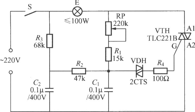
To address the lag and light transition issues, a Triac dimming light circuit featuring a dual time constant can be employed. This circuit enhances the resistor-capacitor network formed by R3 and C2. The reduced charge on capacitor C1 can...
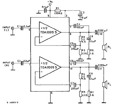
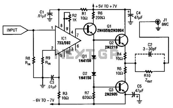
The TDA2005 car audio amplifier circuit is specifically designed for use in devices such as car radios, CD players, and similar equipment. This amplifier is based on the TDA2005 audio integrated circuit (IC), capable of delivering a maximum output...