
Ultrasonic Cleaner Circuit

The ultrasonic cleaner circuit is designed to facilitate the removal of contaminants from delicate items using high-frequency sound waves. The core components of the circuit include a microcontroller, piezoelectric transducers, a power oscillator, and a rectification stage.
The microcontroller serves as the central control unit, managing the timing of the ultrasonic cleaning cycles and providing a digital readout of the operational status. It can be programmed to set various cleaning durations, allowing users to customize the cleaning process according to the specific requirements of the items being cleaned.
The power oscillator, designated as Q1 in the circuit, generates the ultrasonic frequency necessary for effective cleaning. Operating within the range of 40 to 60 kHz, this frequency is optimal for creating cavitation bubbles in the cleaning solution. These bubbles implode upon contact with the surfaces of the items, dislodging dirt and contaminants without causing damage.
The piezoelectric transducers, RESL and RES2, convert the electrical signals from the power oscillator into mechanical vibrations. These vibrations propagate through the cleaning solution, creating the ultrasonic waves that facilitate the cleaning process. The arrangement and positioning of these transducers are critical for achieving uniform ultrasonic coverage within the cleaning tank.
The bridge rectifier-capacitor input filter converts the AC line voltage into a suitable DC voltage for powering the oscillator. This stage ensures that the circuit operates efficiently and reliably, providing a stable power supply to the oscillator and transducers.
Overall, this ultrasonic cleaner circuit is a sophisticated yet practical solution for efficiently cleaning delicate items, leveraging the principles of ultrasonic technology to achieve superior cleaning results. Ail ultrasonic cleaner is useful to clean certain items. This circuit uses a microcontroller to control timing and give a digital readout, but only the basic oscillator can be used, if desired. RESL, RES2 are piezoelectric transducers driven by power oscillator Ql. Ql is powered by a bridge rectifier-capacitor input filler that operates directly off the ac line. The frequency is 40 to 60 kHz.
Related Circuits
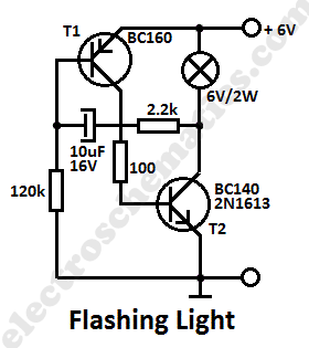
This simple flashing light circuit operates at 6 volts and 0.5A, exhibiting low current consumption when the light bulb is turned off. The frequency of the flashing is predetermined. The circuit consists of a power supply, typically a battery or...
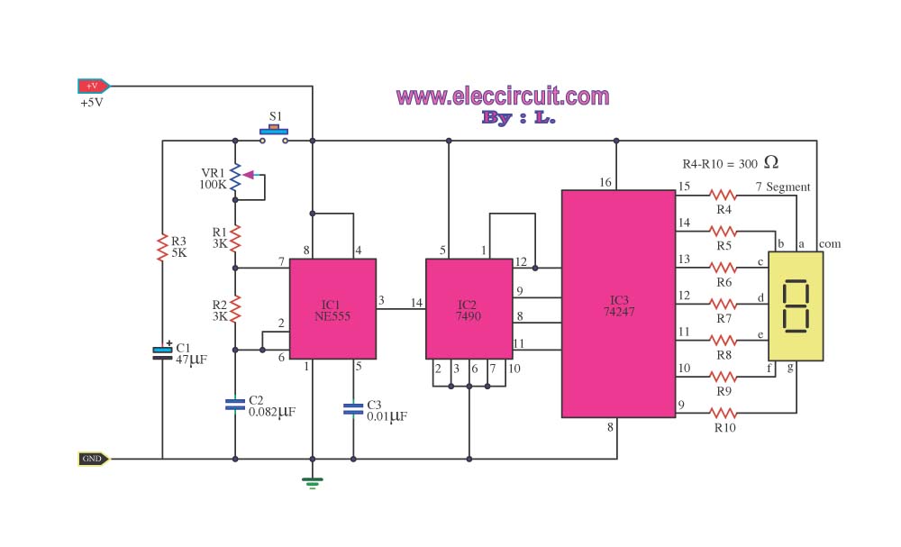
This digital dice circuit is designed to display numbers effectively. When the spin switch is turned off, it converts the input into a binary format using a diode matrix composed of diodes D1 to D9 (1N4148 or 1N914). This...
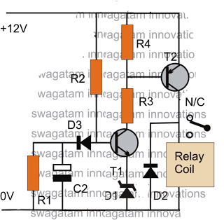
The post discusses a simple delay ON circuit that enables a connected load at the output to be activated with a predetermined delay after the power switch is turned ON. This circuit can be utilized in various applications that...
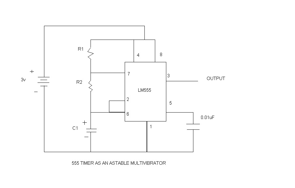
An astable multivibrator, commonly referred to as a free-running multivibrator, is a circuit that generates rectangular waves without the need for external triggering. The timing characteristics of this circuit are determined by the values of the resistors and capacitors...
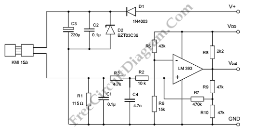
A modulated current is supplied by the integrated rotational speed sensor KMI 15/x. This current signal needs to be converted into a ground-referenced voltage signal. The KMI 15/x sensor operates by generating a modulated current proportional to the rotational speed of...
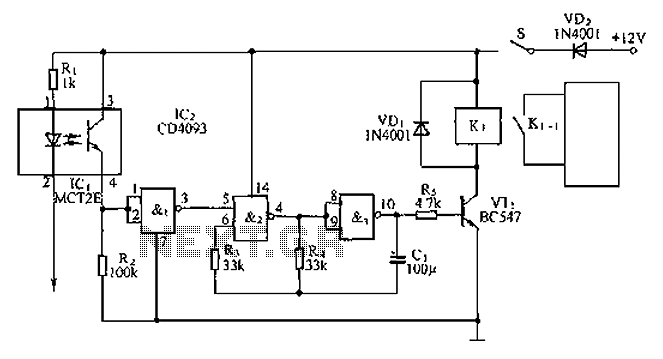
An anti-theft car audio system circuit is depicted, powered by a 12V DC supply from the car battery. Upon closing switch S1, the light-emitting diode in optocoupler IC1 activates, causing the phototransistor to conduct. This results in a high-level...