
OEM AUX Light Switch Diagram

The schematic for the OEM AUX switch wiring involves several key components and connections that ensure proper functionality and safety. The green LED indicator (pins 1 and 2) provides visual feedback when the switch is engaged, enhancing user experience and awareness of the switch status. The choice of wiring gauge (14-16 for the switch and 8-12 for the lights) is critical to handle the current loads without overheating or voltage drops.
The operational flexibility provided by pin 3 is a significant advantage, allowing users to choose between constant power from the battery or switched power from other circuits. This decision directly impacts the usability of the AUX lights and should be made based on the intended application. The relay acts as a crucial intermediary, allowing low-power switch signals to control high-power loads without risking damage to the switch itself.
The backlight functionality (pins 5 and 6) is a thoughtful addition that improves visibility in low-light conditions, contributing to overall safety and ease of use. The integration with existing vehicle wiring, such as the ATRAC switch, allows for a cleaner installation without the need for extensive modifications.
In summary, the schematic design for the OEM AUX switch is characterized by its user-centric features, operational flexibility, and compatibility with existing vehicle systems, making it an effective solution for enhancing vehicle functionality. Proper attention to wiring practices and component selection will ensure reliable performance and longevity of the installed system.I decided to throw together a schematic of how the OEM AUX switch should be wired, and print it so that when I install the wiring I would have a handy reference. Figured I would post it. Here is another breakdown of the switch pins, keeping in mind that thepin layout is labeled while looking INTO the terminals, with the locking tabs on the
Pins 1 and 2 are the power and ground for the green LED built into the switch. When the switch is depressed, this little LED lights up and tells you that the switch in "ON". Basically a little indicator. 14-16 gauge wire is fine. Pins 3 and 4 make up the switching circuit. You have a choice from where you would like your pin 3 supply to come from, and your decision will determine the opperational conditions of the lights. Again, 14-16 gauge wire. If you wire pin 3 from the battery/fuse panel, you will be able to use the AUX lights ANYTIME, ignition on or off.
Good choice if you want to illuminate something with the car off. However, if you forget about them being on and go to bed, your FJ`s battery is going to be dead in the morning. Additionally, you can wire pin 3 from any 12V supply wire on the vehicle, but be aware that the AUX lights will only operate when that specific supply wire is active.
Pin 4 is the output to the relay. On the relay, there will be a picture of a little internal coil and switch, and labels for which pins are which. Wire pin 4 of the AUX switch to one of the pins on the relay that connect to the internal coil circuit.
The other pin on the relay of this coil circuit should be grounded. Pins 5 and 6 serve as the gound and supply for the backlight of the switch, meaning that whenever your interior lights are on, you will see the switch lit up similar to the ATRAC switch. As an easy hook up, tap the wire coming from the AUX switch pin 5 to the white/greentrace wire coming out of the ATRAC switch.
Then, tap AUX pin 6 to the green wire coming out of the ATRAC switch. 14-16 gauge, if needed, is fine. A couple more notes, the KC lights and their respective wiring should be in the 8-12 gauge range, considering these lights are rated at 135W. Also, the optional fuse panel is a good idea if you want to keep all wiring seperate from the stock circuits.
Tons of good threads about them, too. I did what you guys are trying to do. While there are probably a number of ways to do it, here are some options. It depends how reversible you want to make it. I chose the medium option. Remove the radio bezel to get at the switches in the center switch bank. Disconnect the plug from the back of the AUX switch. Wire the new switch harness per directions in this post or original post which is linked to in this post. Essentially you need to tap power off the head/marker lamp. This becomes the power used for the backlight of the switch and power used to latch the relay. Find the connector bewteen the harness coming from the firewall and the harness coming from the lights (located on the driver`s side right over the wheel well).
Cut the harness on the LIGHT side of the connector leaving you enough to splice the connector back on later if needed. If you dont like this option buy a new lamp harness and cut the connector off it. There are two wires in the lamp harness. These are power and ground. The ground I think has a black stripe. Ground the ground to a body ground. Take the power wire for the lights and connect to the light terminal on the relay. You should have 3 more terminals on your relay. One is ground, ground it. The other two are power from battery, so connect to red side of battery. Last terminal is line from switch. Here is it in words: The only thing you have to be careful of is the red/green trace wire. It looks like there is a diode shrink wrapped in line. I expect this is to prevent feeding power to the switch from the re 🔗 External reference
Related Circuits
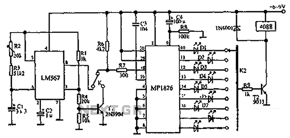
The circuit illustrated in the figure incorporates the MP1826 as a multi-stage divider. The LM567 serves as the frequency demodulation component, functioning as a dual-band oscillator that generates the desired low-frequency pulse from the MP1826. The oscillation center frequency...
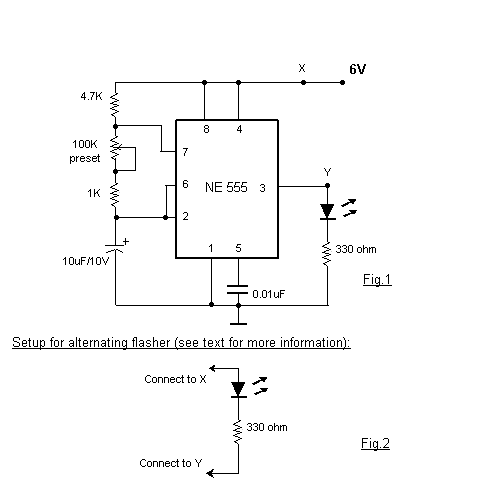
This circuit is a basic design for flashing one or more LEDs, as well as for alternately flashing multiple LEDs. It employs a 555 timer configured as an astable multivibrator, allowing for variable frequency operation. When the preset is...
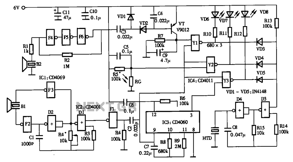
The timing circuit utilizes an electronic switch composed of F1, F2, and VT1 to reduce quiescent current to approximately 1 to 2 A with the 555 timer. Upon initial power-up, the voltage across capacitor C2 cannot instantly change, causing...
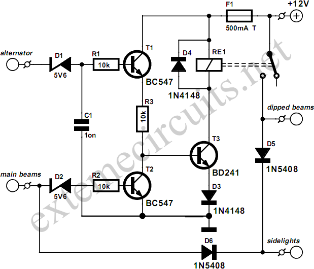
This circuit ensures that the car's lights will automatically activate when the engine is running, preventing the driver from forgetting to turn them on. The dipped beams and sidelights are engaged automatically, while the dipped beams turn off when...
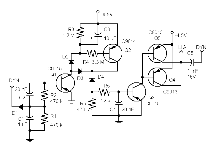
This stand-light features a 1000 µF capacitor (C5) that connects the dynamo to the lights. The capacitor cuts off power to the lights at low speeds. While this effect may be negligible for a bottle dynamo, it could be...
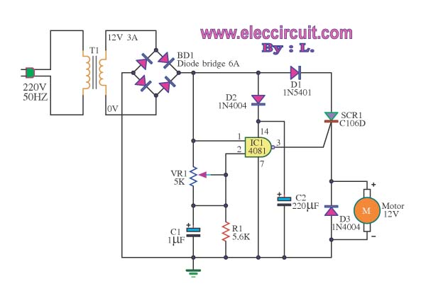
This is a speed motor controller circuit for a 12V DC motor. The speed of rotation of the spindle motor can be adjusted from 5 to 60 cycles per minute. The speed motor controller circuit for a 12V DC motor...