
On-off Infrared Remote Control

The circuit design incorporates several key components that facilitate its operation. The Sony SBX 1620-52 infrared receiver is sensitive to a wide range of infrared signals, ensuring compatibility with various remote controls. The use of T1 as an inverter allows the received pulses to be conditioned appropriately for triggering the D flip-flop, IC2A. The monostable configuration of IC2A ensures that a single pulse is produced for each activation, providing a clean and controlled output.
The output from IC2A is fed into IC2B, which acts as a toggle mechanism for the LED indicator within IC3. This LED serves as a visual confirmation of the circuit's state, indicating whether the load is on or off. The opto triac configuration in IC3 is crucial for achieving silent operation, as it allows for the switching of AC loads without generating electrical noise, which can be disruptive in a home theater environment.
The choice of triac T2 is significant, as it must be capable of handling the load's current without overheating or failing. The flexibility to select a more powerful triac provides scalability for different applications, whether for lighting or other household devices.
Powering the circuit directly from the mains via a class X or X2 capacitor ensures safety and efficiency. These capacitors are designed to withstand high voltages and provide self-healing properties, reducing the risk of failure over time. The requirement for proper insulation in housing the circuit cannot be overstated, as safety is paramount when dealing with mains voltage.
Overall, this circuit represents an innovative solution for managing lighting in environments where infrared remote controls are prevalent, enhancing the user experience while ensuring safety and reliability.Most homes today have at least a few infrared remote controls, whether they be for the television, the video recorder, the stereo, etc. Despite that fact, who among us has not cursed the light that remained lit after we just sat down in a comfortable chair to watch a good film This project proposes to solve that problem thanks to its original app
roach. In fact, it is for a common on/off switch for infrared remote controls, but what differentiates it from the commercial products is the fact that it is capable of working with any remote control. Therefore, the first one you find allows you to turn off the light and enjoy your movie in the best possible conditions.
The infrared receiver part of our project is entrusted to an integrated receiver (Sony SBX 1620-52) which has the advantage of costing less than the components required to make the same function. After being inverted by T1, the pulses delivered by this receiver trigger IC2a, which is nothing other than a D flip-flop configured in monostable mode by feeding back its output Q on its reset input via R4 and C3.
The pulse that is produced on the output Q of IC. 2A makes IC. 2B change state, which has the effect of turning on or turning off the LED contained in IC3. This circuit is an opto triac with zero-crossing detection which allows our setup to accomplish switching without noise. It actually triggers the triac T2 in the anode where the load to be controlled is found. The selected model allows us to switch up to 3 amperes but nothing should stop you from using a more powerful triac if this model turns out to be insufficient for your use.
In order to reduce its size and total cost, the circuit is powered directly from the mains using capacitor C5 which must be a class X or X2 model rated at 230 volts AC. This type of capacitor, called self-healing`, is the only type we should use today for power supplies that are connected to ground.
Traditional` capacitors, rated at 400 volts, do not really have sufficient safety guarantees in this area. Considering the fact that the setup is connected directly to the mains, it must be mounted in a completely insulated housing.
A power outlet model works very well and can easily be used to inter-space between the grounded wall outlet and that of the remote control device. Based on this principle, this setup reacts to any infrared signal and, as we said before, this makes it compatible with any remote control.
On the other hand, it has a small disadvantage which is that sometimes it might react to the normal` utilization of one of these, which could be undesirable. To avoid that, we advise you to mask the infrared receiver window as much as possible so that it is necessary to point the remote control in its direction in order to activate it.
🔗 External reference
Related Circuits
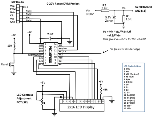
This project details the construction of a digital voltmeter utilizing a PIC microcontroller. A character-based HD44780 LCD display is employed to visualize voltage measurements. The microcontroller selected for this project is the PIC16F688, which features 12 I/O pins, with...
This transmitter utilizes a 5089 DTMF generator chip along with a keypad to produce DTMF signals, which are then modulated onto an infrared (IR) light beam emitted from an IR LED. The circuit employs a 3.579-MHz TV burst crystal...
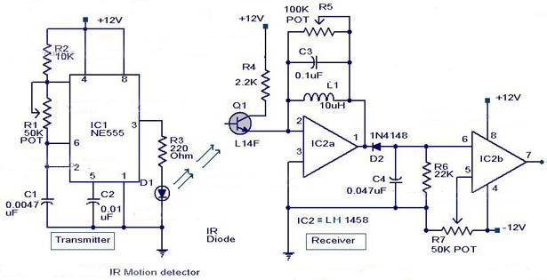
An infrared motion detector alarm is designed to activate whenever a person enters its infrared detection zone. This sensor detects the movement of a human body, triggering an automatic alarm. The detection zone has a horizontal coverage of 80...

The TLE6282G is an H-Bridge and Half Bridge Driver IC designed for high-current DC brush motor applications in PWM control mode. It is suitable for use in injector and valve applications across 12V, 24V, and 42V power networks. This...
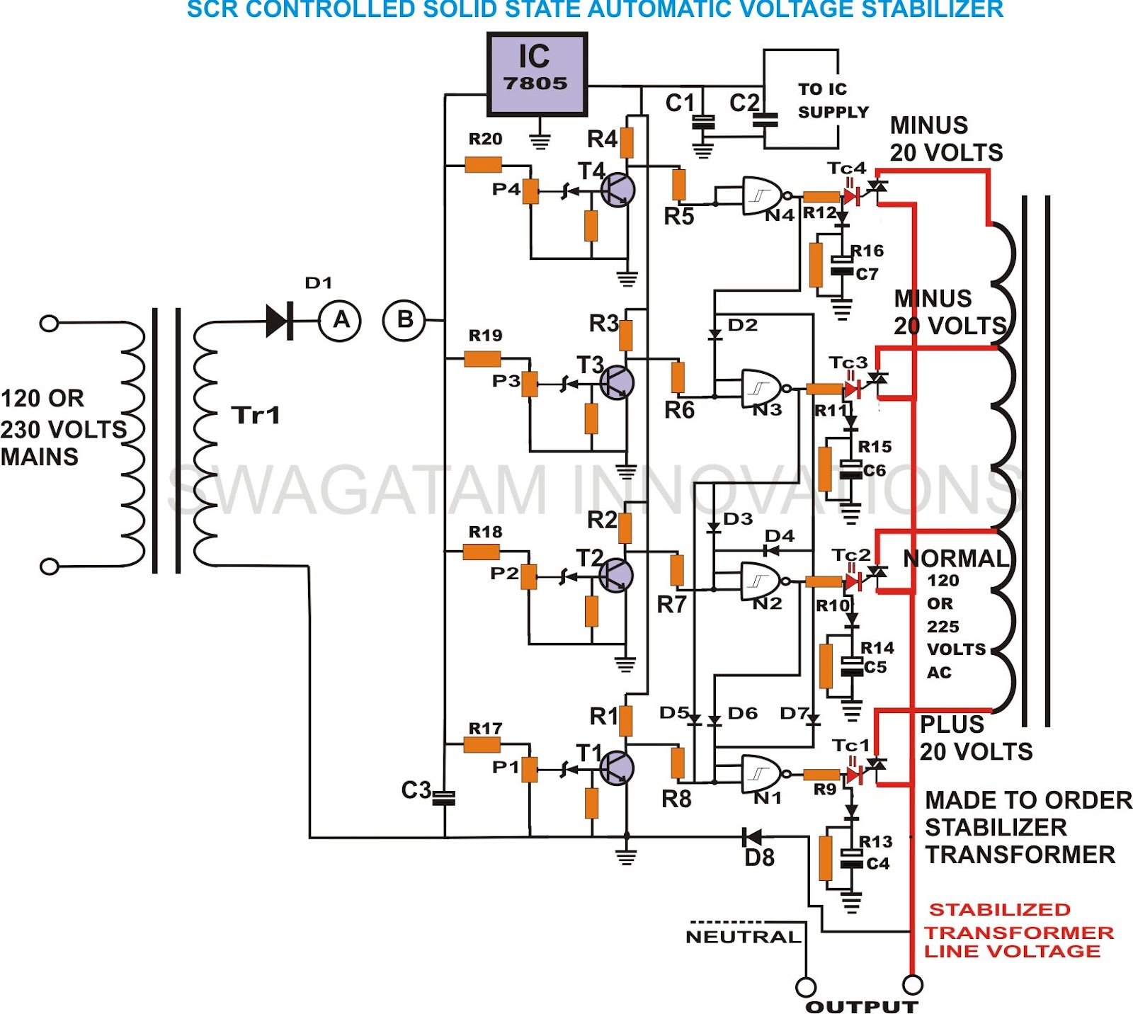
This unique and hard-to-find triac-controlled AC voltage stabilizer circuit has been specifically designed for efficient voltage stabilization. With a solid-state design, the voltage switching transitions are smooth, resulting in minimal wear and tear. The proposed circuit provides four-step voltage...
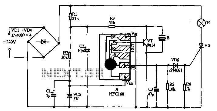
220V AC power is supplied through a VD1 to VD4 bridge rectifier and a voltage regulator circuit involving R1, R2, and VD5 components. The output provides a DC voltage of approximately 3V, which powers the manifold A. The manifold...