
THREE RANGE LIGHT METER

The described circuit functions as a photo exposure meter, designed to provide accurate light measurements. The Clairex 905HN light-dependent resistor (LDR) serves as the sensor, responding to varying light levels by changing its resistance. This change is detected by the DC differential amplifier, which amplifies the signal for improved readability on the meter.
The calibration procedure outlined in the article is critical for ensuring that the meter provides accurate readings across its scale. This process involves connecting specific resistors to the photocell jack P1, which allows the user to adjust the meter's response to light levels, ensuring that the readings are linear and proportional to the light intensity.
The inclusion of a switching circuit to monitor the 22.5-V battery is an essential feature, as it ensures that the circuit remains functional and accurate. If the 4.5-V battery, which may be used for other components, is low, the circuit will not be able to achieve a full-scale adjustment, potentially leading to inaccurate readings. Therefore, maintaining the battery voltage is crucial for the reliability of the meter.
In summary, this electronic schematic is designed for accurate light measurement, with a focus on calibration and battery monitoring. The integration of the Clairex 905HN light-dependent resistance element with a DC differential amplifier and a calibrated meter provides a robust solution for photo exposure measurement, making it suitable for various applications in photography and lighting analysis.Uses probe containing Clairex 905HN light-dependent resistance element, connected to DC differential amplifier driving meter having specially calibrated scale. Article gives calibration procedure. Switching circuit provides constant check on voltage of 22. 5-V battery. If 4. 5-V battery is low full-scale adjustment cannot be made Resistors having values specified in article are connected in turn to terminals of photocell jack P1 for calibration that gives linear scale reading. -J. L. Mills, Jr. , Light Right Do-It-Yourself Photo Exposure Meter, 73 Magazine, Sept. 1978, p 204 206 and 208-211. 🔗 External reference
Related Circuits
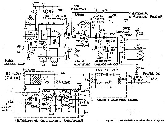
A deviation monitor can be constructed by connecting a frequency modulation (FM) detector to an AC voltmeter, calibrating the meter in units of frequency deviation. One method for detecting or demodulating the FM signal is via a phase-locked loop...
Pulses are received by the timer from the distributor points. When the timer output is high, Meter M receives a calibrated current through R6. The meter does not... The circuit described involves a timer that receives pulse signals from distributor...
The function of this circuit is to detect a sudden shadow falling on the light sensor and to activate a buzzer when this occurs. The light sensor is designed to monitor ambient light levels. The circuit utilizes a light-dependent resistor...
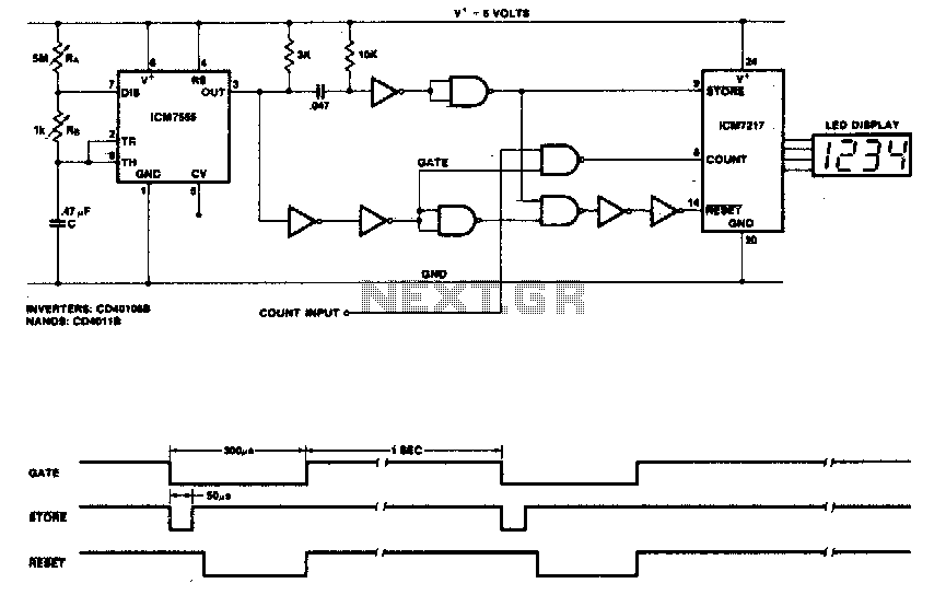
This circuit utilizes the low-power ICM7555 (CMOS 555) to generate the gating, STORE, and RESET signals. The timer is configured as an astable multivibrator to provide the gating signal. Calibration of the system is achieved using a 5 MΩ...
The circuit is placed parallel with the exit of power amplifier and gives the level of signal from output. Changing resistance R1 in the input circuit, we adapt the indication of power in the resistance of loudspeaker that we...
The circuit consists of inverter and charger sections. The inverter section utilizes the NE555 timer, while the charger section is based on the LM317 adjustable regulator. In the inverter section, the NE555 is configured as an astable multivibrator, generating...