
One-IC two-tones Siren

This circuit incorporates a sound generation mechanism that utilizes integrated circuits (ICs) to produce various sound effects. The primary components include two sets of operational amplifiers (IC1A, IC1B) that create the dual-tone sound reminiscent of emergency vehicles. The sound output is modulated by the configuration of the capacitors and resistors, which define the frequency and amplitude of the tones produced.
The implementation of switch SW1 allows the user to toggle between two distinct sound profiles: a police/fire siren and an old-fashioned siren. The transition between these sounds is facilitated by the oscillators IC1C and IC1D, which are activated by the push button P1. This feature provides an engaging interactive element for children, enabling them to control the sound output.
The loudspeaker selection is crucial for sound quality. It is recommended to use a loudspeaker with adequate power handling capabilities to ensure that the output is both realistic and loud enough for outdoor use. Proper casing of the loudspeaker will help in amplifying the sound and preventing distortion.
To customize the sound further, users can experiment with the values of capacitors C1, C2, C5, and C6, as well as the associated resistors. Adjustments to these components will allow for fine-tuning of the pitch and duration of the generated tones, providing a versatile audio experience.
The circuit's design prioritizes low power consumption, making it suitable for battery-operated applications. By not incorporating a dedicated power switch, the circuit can remain in a low-power state when not actively generating sound, ensuring efficient energy use. This feature is particularly beneficial for portable devices where battery longevity is a concern.This circuit is intended for children fun, and is suitable to be installed on bicycles, battery powered cars and motorcycles, but also in models and other games. With SW1 positioned as shown in the circuit diagram it reproduces the typical dual tone sound of Police or Fire-brigade cars, by the oscillation of IC1A and IC1B gates.
With SW1 in the ot her position, the old siren sound increasing in frequency and then slowly decreasing is reproduced, by pushing on P1 that starts oscillation in IC1C and IC1D. The loudspeaker, driven by Q1, should be of reasonable dimensions and well encased, in order to obtain a more realistic and louder output.
Tone and period of the sound oscillations can be varied changing the values of C1, C2, C5, C6 and/or associated resistors. There is no power switch: leave SW1 in the low position (old-type siren) and the circuit consumption will be negligible.
🔗 External reference
Related Circuits
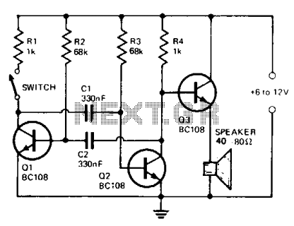
The circuit comprises a multivibrator (Q1 and Q2) and a low-power output stage (Q3). The speaker should have an impedance ranging from 40 to 80 ohms. To accommodate a low-impedance speaker, an output transformer should be connected from the...
This circuit produces a sound similar to a factory siren. It makes use of a 555 timer IC used as an astable multivibrator of a center frequency of about 300Hz. The frequency is controlled by pin 5 of the...
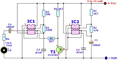
Browse home alarm circuit explanation latest schematic siren wailing with latest Wailing Alarm Siren circuit schematic with explanation. The loudspeaker LS and the resistor marked Rx should be together 75 ohms. If a standard 8-ohm speaker is used, then...
The objective of this project was to create a custom device utilizing local manufacturing resources. At that time, there was a pressing need for a Dub Siren. A circuit diagram was located, and with the assistance of an electronics...
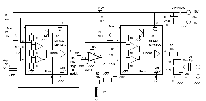
This circuit produces a sound similar to the police siren. It makes use of two 555 timer ICs used as astable multivibrators. The frequency is controlled by the pin 5 of the IC. The first IC (left) is wired...
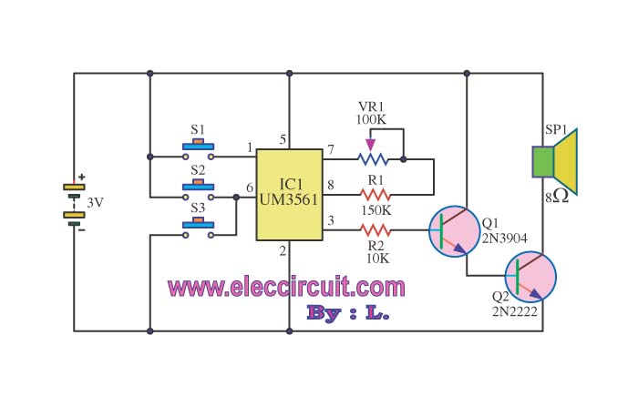
The circuit operates using a UM3516 integrated circuit (IC1), which is designed to generate sound. The output sound is produced at pins 7 and 8 of IC1, and the components R1 and VR1 are utilized to control the frequency...