
Optical toggle switch using a single Chip

The optical toggle switch circuit utilizes the CD4027 dual flip-flop IC, which is capable of toggling its output state based on the input clock pulses. The CD4027 consists of two independent flip-flops, allowing for versatile applications in digital logic designs. The integration of a 555 timer configured in a monostable mode serves to create precise timing pulses that act as the clock signal for the flip-flops.
In this configuration, the output of the 555 timer can be connected to the clock input of the CD4027, where each pulse from the timer will toggle the state of the flip-flop. This setup can be particularly useful in applications where optical isolation is required, as the optical components can control the toggle action without direct electrical connections, thereby enhancing safety and reducing noise interference.
The circuit can be powered using a standard DC power supply, and the output from the flip-flop can be used to drive other components, such as LEDs or relays, to indicate the toggle state. The design can be further enhanced by adding additional features such as debounce circuits or LED indicators to provide visual feedback of the switch status.
Overall, this optical toggle switch circuit provides a reliable and efficient method for controlling electronic devices with minimal components, making it suitable for various applications in automation, remote control systems, and more.Optical toggle switch using a single Chip. Using dual flip-flop IC CD4027 employ a 555 based monostable circuit to supply input clock pulses. The circuit described here obviates this requirement. One. 🔗 External reference
Related Circuits

A control program typically requires more than simply turning outputs on and off; these actions are triggered by events. Such events are connected to the input of a microcontroller, which determines the subsequent actions. Inputs can originate from various...

This metal detector circuit project is a simple design based on common electronic components. It utilizes transistors to provide a visual indication through an LED and an acoustic signal to alert users when metal is detected. To calibrate the...
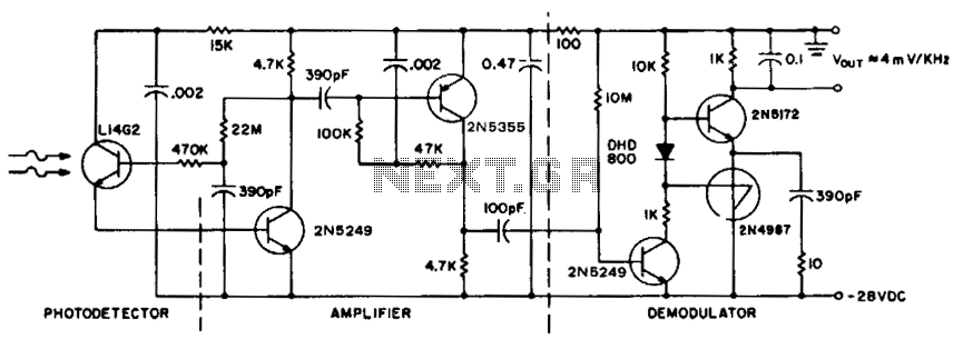
To achieve maximum range, the receiver should be constructed similarly to a radio receiver front end, as the signals received will exhibit comparable frequency components and amplitudes of the photodiode current. The primary limitation on the receiver's performance is...
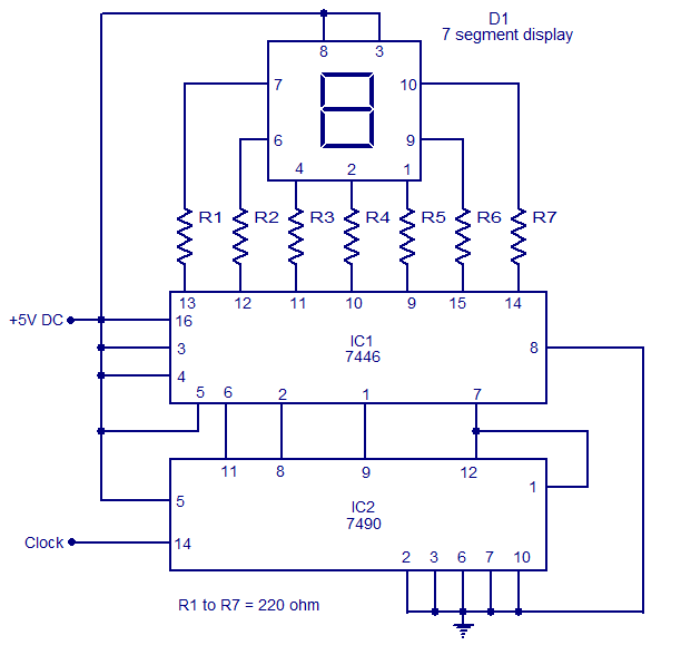
The circuit presented is a basic static 0-9 display that can be utilized in various applications. It is based on the 7490 asynchronous decade counter (IC2), a 7-segment display (D1), and a seven-segment decoder/driver IC 7446 (IC1). The seven-segment...

This circuit was formed to create a wireless alarm from a normal magnetic contact. By fixing the magnet to the leaf of a door, or swing of a drawer, it is easy to reveal the opening. To transmit the...

The LM628 and LM629 dedicated motion-control processors can be utilized to design various applications involving DC and brushless DC servo motors, as well as other servomechanisms. The power path of this electronic project, which functions as a motor driver,...