
optimized 6 element uhf yagi antenna

The antenna design described involves a configuration where the elements are strategically arranged to optimize performance while maintaining flexibility in component sizing. The choice of element diameters, specifically the 5.8 mm for the antenna elements and the recommended 12 mm for the dipole, allows for a balance between structural integrity and electrical characteristics.
The boom serves as a central support structure, providing mechanical stability and facilitating the electrical connection of the elements. This configuration ensures that all elements, except the dipole, are grounded to the boom, which minimizes interference and enhances signal quality. The mounting options—either on top of or through the boom—offer versatility in installation, allowing for customization based on specific application requirements or environmental conditions.
In practice, this antenna design can be utilized in various applications, including amateur radio, television reception, and other communication systems. The ability to maintain the same length and spacing while varying the diameters of the elements simplifies the tuning process and reduces the need for extensive recalibration. This feature is particularly advantageous in field applications where quick adjustments are necessary.
Overall, the described antenna configuration presents a robust solution for achieving effective communication while allowing for adaptability in its physical design. The careful consideration of element size and mounting techniques contributes to the overall efficacy of the antenna system.The elements diameter of the antenna may vary between 5. 8mm and the dipole diameter may vary between 8. 12mm (12mm recommended) without the need of changing anything to the length or spacing. All elements except the dipole are electrically connected to the boom and may be mounted on top or through it.
Related Circuits
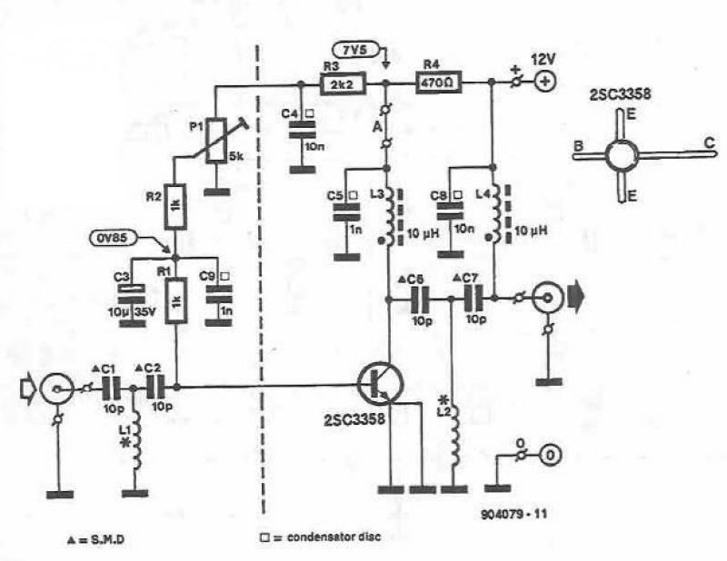
This UHF amplifier circuit project is beneficial for enhancing weak TV signals. The amplifier provides a gain of 10-15 dB within a frequency range of 400 to 850 MHz. To ensure optimal performance and reliability, the PCB tracks should...
This article provides an overview of the R100 and MCR100 UHF repeaters. All information was obtained from a physical examination of the station, the programming software, and the R100 Instruction (and service) Manual, p/n 6881078E15, as well as the...
This UHF transmitter is designed for low power applications such as remote controls for garage doors, operating systems, and wireless alarms. This UHF FM transmitter is equipped with... This UHF transmitter operates within the Ultra High Frequency (UHF) band, which...
This document provides information on utilizing the ATA6833-DK for Brushless DC (BLDC) Motor Control applications. The BLDC Motor Control Kit includes two boards: a Basic board featuring a BLDC Gate Driver System Basis Chip (SBC) ATA6833 and ATA6834, along...
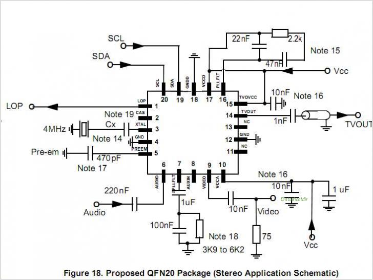
MC44BS374CA: PLL Tuned UHF and VHF Audio Video High Integration Modulator MC44BS374CA The MC44BS374CA Audio and Video Modulator is for use in VCRs, set-top boxes, and similar devices. By Freescale Semiconductor, Inc The MC44BS374CA is a highly integrated audio and...
This circuit is designed to be used in conjunction with the standard 4 foot square loop used in MW for long distance reception. The described circuit is intended for use with a standard 4-foot square loop antenna, optimized for medium...