
Q- Multiplying Loop Antenna

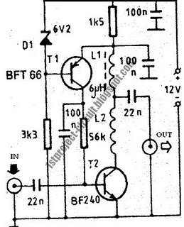
The described circuit is intended for use with a standard 4-foot square loop antenna, optimized for medium wave (MW) radio reception over long distances. The square loop antenna is characterized by its simplicity and effectiveness in capturing electromagnetic waves, particularly in the MW frequency band.
The circuit typically consists of an impedance matching network to ensure maximum power transfer from the antenna to the receiver. This network can include components such as capacitors and inductors arranged in a specific configuration to resonate at the desired frequency range.
Additionally, the circuit may incorporate a low-noise amplifier (LNA) to enhance the weak signals received by the loop antenna. The LNA is strategically placed close to the antenna to minimize signal loss due to cable attenuation. The output of the LNA can be fed into a bandpass filter, which helps to eliminate unwanted frequencies and noise, ensuring that only the desired MW signals are processed.
Power supply considerations are also crucial, as the circuit should be designed to operate efficiently with low power consumption, particularly if it is intended for portable or remote applications. The power supply circuit may include voltage regulators to provide stable operating conditions for the LNA and other active components.
Overall, this circuit design is aimed at improving the performance of medium wave reception, utilizing the unique characteristics of the 4-foot square loop antenna for optimal signal capture and processing.This circuit is designed to be used in conjunction with the standard 4 foot square loop used in MW for long distance reception. 🔗 External reference
Related Circuits
This document does not aim to provide an extensive account of the integrated circuits (ICs) used in this circuit. For additional information on this topic, please refer to the "Flip-Flop Made With A LM556 Timer Chip" section and the...
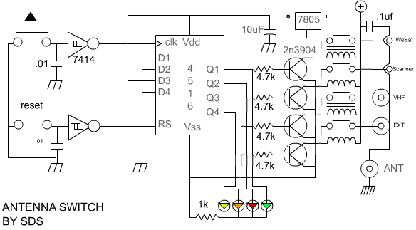
The author described assembling this circuit on a 1"*1" perf board, I actually laid out a small PC board with excellent results. In this era of surface mount components, I think a much smaller version can be laid out...
A current loop transmitter refers to a sensor system utilized in industrial 4-20mA current loop technology. This transmitter contains the... A current loop transmitter is a critical component in industrial automation and control systems, particularly in applications where analog signal...
This HD TV UHF wideband amplifier (Ultra High Frequency amplifier) provides a total gain of 10 to 15 dB within the frequency range of 400 to 850 MHz, making it suitable for areas with weak television signals. To ensure...
A use has been found for a collection of DIP-style RF relays acquired from a discount electronics shop. These relays are completely sealed and RF shielded, featuring low contact capacitance, making them suitable for VHF frequencies. They operate at...
This design presents a simple antenna amplifier electronic circuit project, which can be utilized based on the provided circuit diagram. The antenna amplifier operates effectively within a frequency range of 1 to 300 MHz. It is suitable for high...