
Oscillating output improves system security

The described circuit utilizes a dynamic variable signal to enhance the security of digital outputs in electronic control systems. The implementation involves a transistor, which acts as a switch, controlled by an oscillating signal that represents a logic-high state. This oscillating signal is advantageous over a constant voltage level as it adds a layer of complexity, making it more difficult for unauthorized access or signal interception.
In the circuit, the output transistor is typically an NPN or PNP type, depending on the design requirements. The dynamic variable signal is fed into the base of the transistor, causing it to switch on and off in accordance with the oscillation frequency of the input signal. When the transistor is in the 'on' state, current flows from the collector to the emitter, allowing the pulse transformer to operate. The pulse transformer is essential for isolating the control system from the load, providing voltage step-up or step-down capabilities, and enhancing signal integrity.
The pulse transformer is connected to the collector of the output transistor. It converts the pulsating current into a corresponding output voltage, which can be used to drive other components or systems. The design of the pulse transformer must be carefully considered, including its turns ratio, core material, and frequency response, to ensure effective operation with the oscillating signal.
This approach not only improves security but also allows for better noise immunity and signal fidelity in the control system's output, making it suitable for various applications, including industrial automation, automotive systems, and consumer electronics. The careful selection of components and design parameters is crucial for achieving optimal performance and reliability in the final circuit.Many electronic-control systems have digital outputs that use transistors. One method of improving the security in these outputs is to use an oscillating signal to represent a logic-high state instead of a fixed voltage level (Figure 1). This type of signal, a dynamic variable, can drive the circuit shown in Figure 2. This circuit connects to the output transistor of the electronic-control system. The dynamic- variable signal connects to the output transistor, whose collector connects to a pulse transformer.
🔗 External reference
Related Circuits
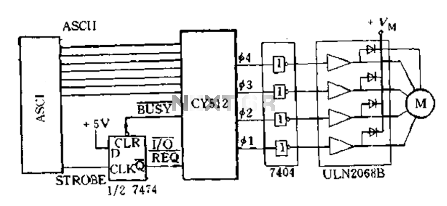
The CY512 is an easily developed system that operates using ASCII keyboard code. It features three operating modes: 1) Immediate command execution mode, where users can input ASCII commands to directly control the stepping motor movement in decimal stepping...
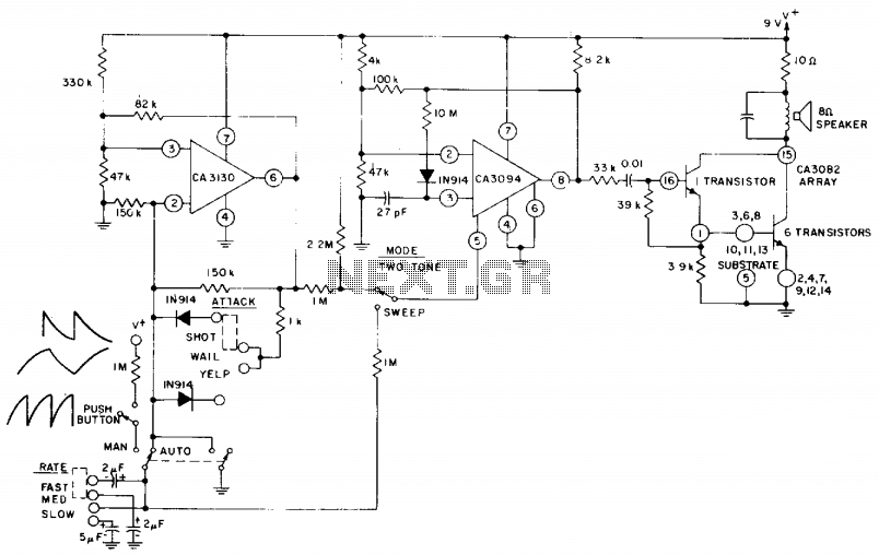
The circuit utilizes a CA3130 BiMOS operational amplifier configured as a multivibrator to regulate the siren's frequency. A CA3094 is employed as a voltage-controlled oscillator (VCO), which is subsequently connected to a CA3082 transistor array that drives a speaker....
In certain versions of the circuit, the input buffer may be completely absent, while in other versions, the buffer transistors exhibit different biasing configurations or utilize different transistors altogether. Some designs contain significant errors, including biasing issues and incorrect...

A simple method for generating a low-power voltage supply of opposite polarity from the main supply. A self-oscillating driver produces pulses at a repetition frequency of 100 kHz. When the VMOS device is off, capacitor C is charged to...
A drink mixer inspired by BAR2D2 utilizes a gravity-fed pump that operates on a 9V battery. The circuit incorporates a 555 timer to control the duration of the pump's operation. When connected directly to the battery, the pump functions...
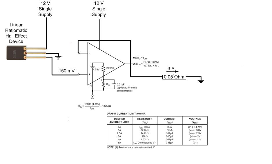
The proposed approach would dissipate (12V)(3A) = 36 watts, which results in significant heat generation in the circuit. This necessitates consideration of two alternatives: 1) Operating the op-amp at a lower supply voltage, if feasible, or 2) Utilizing a...