
Oscillations and Regenerative Amplification using Negative Resistance

The design and operation of L-C oscillators are critical in various electronic applications, particularly in communication and signal processing. The tuned L-C network, composed of inductors (L) and capacitors (C), forms the backbone of these oscillators. The essential principle is to achieve a balance between the energy stored in the magnetic field of the inductor and the electric field of the capacitor, allowing oscillations to occur. The introduction of an active device, such as the Lambda diode, is necessary to compensate for the inherent losses in the circuit. The negative resistance characteristic of the Lambda diode allows it to offset these losses, enabling sustained oscillations.
In practical implementations, the choice of components, such as the inductor and capacitor values, is crucial for determining the oscillation frequency. The feedback mechanism must be carefully designed to ensure that the loop gain approaches unity, which is essential for oscillation initiation. The schematic diagram of the oscillator circuit illustrates the interconnections between the Lambda diode, the L-C network, and any additional components, such as resistors and power supplies, that stabilize the operation.
Furthermore, the performance of the oscillator can be evaluated through its output waveform, which should ideally be a clean sine wave with minimal distortion. The use of an iron-cored inductor and a piezoelectric earphone provides a practical approach to tuning and outputting the oscillation. The regenerative receiver application showcases the versatility of the Lambda diode in enhancing signal reception, emphasizing the importance of selectivity and sensitivity in radio frequency applications.
Overall, the integration of negative resistance devices like the Lambda diode into L-C oscillators represents a significant advancement in electronic circuit design, enabling efficient and reliable oscillation generation for various applications.The usual procedure for the production of sustained oscillations in tuned L-C networks is to overcome circuit losses through the use of designed-in positive feedback or regeneration. Then, during the circuits on-transient oscillations will build up triggered by the thermal noise of circuit elements.
Two possible situations may arise for a potentia l oscillator. The tuned active network may have excess loss, in which case the circuit will refuse to oscillate (Fig. 1-a). Nevertheless, it may still work as a regenerative or high-gain narrow-band tuned amplifier. The second situation that may arise is that of a successful oscillator. In this case, excess loss will have been compensated for (Fig. 1-b) and a sustained oscillation is obtained at the circuits output. In the analog realm, two sine-wave oscillator types are distinguished: the feedback and the negative-resistance oscillator.
Regarding cancellation of resistive losses, both types may be shown to be equivalent, losses being effectively cancelled out by the negative resistance contributed by the active device and associated reactive components. In Fig. 2-a the negative resistance is series connected with the L-C tuned network. Rs represents the tuned circuits series loss. The net resistive loss is RT = Rs - r, and clearly, it may be nulled out. and it also may be nulled out. In this particular case, the net parallel resistive loss would be infinity, meaning zero power losses in the tuned L-C circuit.
If loss cancellation is incomplete, the loop-gain of a sine-wave oscillator will be less than unity and oscillations will not start building up. On the other hand, if the gain is close to unity the circuit will behave as a regenerative or high-gain narrow-band tuned amplifier.
There are a number of single and compound active devices that exhibit negative resistance regions on their static I-V characteristic curves. These devices can be successfully employed in the construction of L-C oscillators and regenerative amplifiers.
One of these devices is the Lambda diode, whose basic configuration is shown in Fig. 3. It makes use of an N-channel and a P-channel JFET, connected in such a way that the drain to source voltage drop of either transistor is the gate to source voltage applied to the other device. Figure 4 shows the measured I-V static characteristic of a Lambda diode implemented by the author with an MPF102 N-channel JFET and a 2N3820 P-channel JFET.
The form of the curve resembles the symbol of the Greek letter lambda. Current sense and voltage polarity are as shown in Fig. 3. Thus, it is a unidirectional device. The author also tested a modified version of the Lambda diode in which a 2N3906 PNP silicon bipolar transistor substituted for the P-channel JFET. The test setup is shown in Fig. 5 and the measured I-V characteristic in Fig. 6. A negative resistance region can be observed to exist between 2Volts and 9Volts (region with a negative ”V1/ ”I1).
Interesting uses for the Lambda diode arise when it is biased on its negative resistance region. Straightforward applications include oscillator circuits and regenerative amplifiers. To prove the usefulness of the modified configuration a simple sine-wave audio oscillator was built around the Lambda diode using an iron-cored inductor and a piezoelectric earphone (Fig. 7). The inductance and the intrinsic capacitance of the earphone tuned the oscillation. The circuit oscillated for power supply values between 3. 2Volts DC and 4. 68Volts DC. The best waveform was obtained for 4. 25Volts DC. A low-distortion sine wave having 2Volts peak was measured across the Lambda diode at a frequency of 909Hz.
The second interesting and successful application was that of a regenerative receiver for the 530kHz~1620kHz MW AM broadcast band. Excellent selectivity and sensitivity, and a smooth regeneration control are appreciated features of this receiver.
The schematic diagram for this 🔗 External reference
Related Circuits
The circuit below is similar to the one above but can be used with a laser pointer to toggle the relay rather than a push button. The IR photo transistor Q1 (Radio Shack 276-145A) or similar is connected to...
This article presents an alternative method for evaluating power supplies that reduces dependency on output voltage and temperature. Traditionally, power supplies have been assessed based on their conversion efficiency, often calculated using commonly used equations. While efficiency serves as...
Most analog multimeters are capable of measuring resistance over a wide range of values, but they can be inconvenient to use due to the reverse reading scale, which is also non-linear. Analog multimeters, often referred to as VOMs (Volt-Ohm-Milliammeter), are...
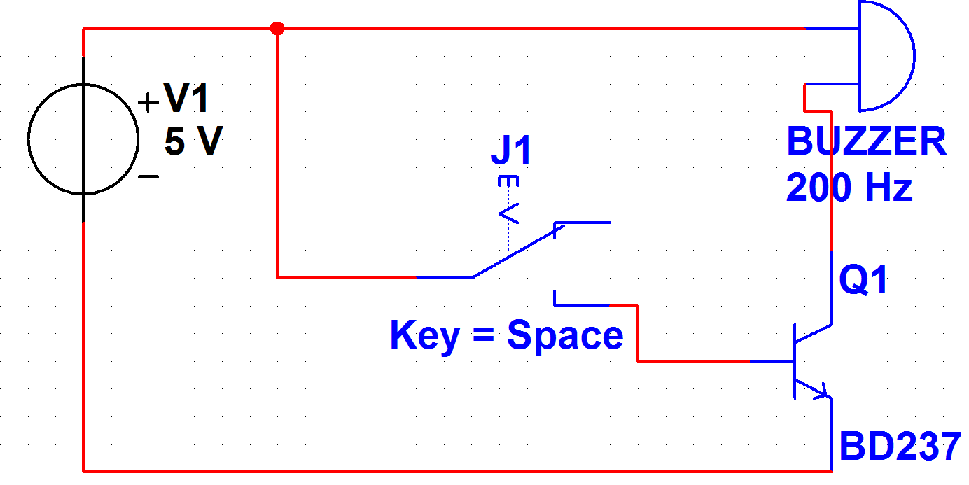
A PB-12N23PW-05Q buzzer is being used with an ATmega 162 microcontroller. Direct connection to the microcontroller pin is not feasible due to the maximum sourcing capability of 20 mA as stated in the ATmega 162 datasheet, while the buzzer...
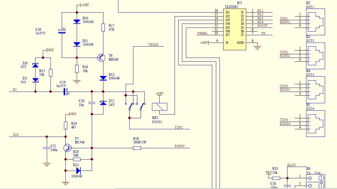
Create a simple telephone-based intercom system in a new house. Shouting between rooms is not effective, and using an instant messaging client or FaceTime lacks the immediacy of a voice call. A collection of old wired telephones is available...
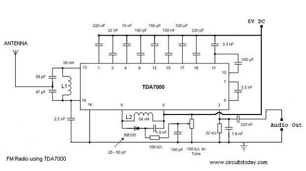
A simple FM radio circuit with a diagram and schematic using the IC TDA 7000. This low-cost single-chip FM radio circuit design is easy to assemble and is suitable for creating a portable FM radio. The FM radio circuit utilizing...