
wien bridge oscillator

The Wien bridge oscillator is a type of electronic oscillator that generates sine waves. It operates based on the principle of phase shift feedback, utilizing a Wien bridge circuit, which consists of resistors and capacitors arranged to create a specific frequency response. The circuit typically includes a combination of resistive and capacitive elements that determine the frequency of oscillation, allowing for precise control over the output frequency.
In a typical Wien bridge oscillator, the configuration includes two resistors and two capacitors forming a bridge circuit. The bridge is balanced at a certain frequency, which is determined by the values of the resistors and capacitors. The feedback loop is crucial for sustaining oscillations; it provides the necessary phase shift and gain to maintain continuous output.
An essential feature of the Wien bridge oscillator is its automatic gain control mechanism, which stabilizes the amplitude of the output signal. This is often achieved using a thermistor or a light-dependent resistor (LDR) that adjusts the resistance in the feedback path based on the output signal's amplitude. This self-regulating aspect allows the oscillator to produce a stable sine wave without requiring manual adjustments.
The output frequency of the Wien bridge oscillator can be calculated using the formula:
\[ f = \frac{1}{2 \pi R C} \]
where \( R \) is the resistance and \( C \) is the capacitance in the bridge. This relationship highlights the importance of selecting appropriate component values to achieve the desired frequency of oscillation.
Applications of the Wien bridge oscillator include audio signal generation, function generators, and as a reference signal in various electronic devices. Its simplicity and reliability make it a popular choice in both educational and professional electronics projects.Wien bridge oscillator. A phase-shift feedback oscillator that uses a Wien bridge as the.. 🔗 External reference
Related Circuits
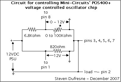
This is a UHF oscillator circuit designed to utilize the Mini-Circuits POS-400+ voltage-controlled oscillator chip. By applying a voltage between 0 to 12V on pin 8, it produces a sine wave output ranging from 200MHz to 380MHz on pin...
You can drop all off the transistors and resistors if your motors don’t drain too much current. You only need a 74F139 or 74S139 NOT the LS version. The chip can provide peak currents up to 100mA for a...
RC oscillators utilize resistors and capacitors to produce low or audio-frequency signals. Therefore, they are often referred to as audio-frequency (A.F) oscillators. RC oscillators are fundamental circuit designs utilized in various applications for generating periodic waveforms, particularly in the audio...
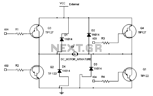
To maintain a constant speed of the motor under varying load conditions, a control application circuit is required. An H-Bridge circuit can be utilized to manage both the speed and direction of the motor. The accompanying diagram illustrates the...
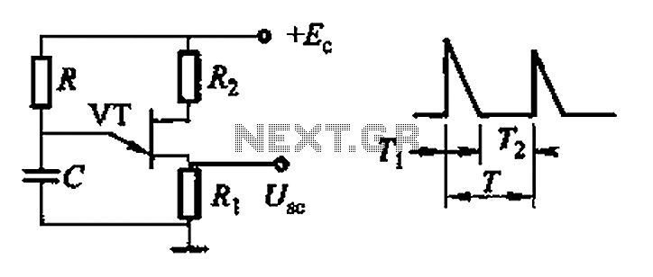
Common non-sinusoidal oscillator circuit, waveform and frequency formula - pulse wave oscillator - blocking oscillator transformer The common non-sinusoidal oscillator circuit is designed to generate pulse waveforms, which are characterized by their square or rectangular shape. These oscillators are...

The total cost will be approximately US$10, which will save space on the circuit board. The design is efficient, but space constraints and budget considerations are a concern. It is possible to eliminate all transistors and resistors if the...