
Oscillator operation-working-feedback circuit block diagram

The feedback amplifier operates on the principle of positive feedback, which is essential for generating sustained oscillations. The closed-loop gain, Af, must exceed unity to ensure that the oscillations can build upon themselves. The positive feedback mechanism allows the amplifier to utilize its own output to drive the input, creating a self-sustaining loop. The resonant feedback circuit plays a crucial role in determining the frequency of oscillation, as it is designed to provide maximum feedback at a specific frequency.
In practical applications, the circuit is often implemented using components such as operational amplifiers, resistors, capacitors, and inductors to form the necessary feedback network. The choice of these components influences the stability and frequency of the oscillation. For instance, the resonant frequency can be calculated based on the values of the inductance and capacitance in the feedback loop, ensuring that the desired frequency of oscillation is achieved.
The behavior of the circuit can be further analyzed through Bode plots or frequency response analysis, which illustrate how the gain and phase shift vary with frequency. This analysis is critical for designing circuits that require precise oscillation characteristics, such as in signal generators, clock circuits, and RF transmitters.
Overall, the feedback amplifier and its associated feedback network are integral to the operation of oscillators, providing a means to generate consistent, repeatable signals without reliance on an external input. The careful design and tuning of the feedback components allow for a wide range of applications in electronic systems.A feedback amplifier having closed-loop gain, Af greater than unity can be obtained by the use of a positive feedback. This result also satisfies the phase condition and thus results in the operation of an oscillator circuit.
An oscillator circuit then provides a constantly varying output signal. If the out put signal varies sinusoidally, the cir cuit can be called as a sinusoidal oscillator. But, if the output voltage rises and drops from one voltage level to another quickly, the circuit can be called a pulse or square-wave genera tor. To understand how an oscil lator produces an output signal without an external input signal, let us consider the feedback circuit shown in fig (a).
In the figure Vin is the voltage of ac input driving the input terminals B-C of an amplifier having voltage gain A. This voltage drives a feedback circuit that is usually a resonant circuit, as we get maximum feedback at one frequency.
The feedback voltage returning to point a is given by equationVf = A ² Vin where ² is the gain of feedback network If the phase shift through the amplifier and feedback circuit is zero, then A ² Vin is in phase with the input signal Vin that drives the input terminals of the amplifier. Now we connect point a` to point b` and simultaneously remove voltage source Vin, then feedback voltage A ² Vin drives the input terminals b c of the amplifier, as shown in fig.
(b). In case A ² is less than unity, A ² Vin is less than Vin and the output signal will die out, as illustrated in second fig. (a). On the other hand if A P is greater than unity, the output signal will build up, as illustrated in second fig.
(b). If A ² is equal to unity, A ² Vin equals Vin and the output signal is a steady sine wave, as illustrated in fig. (c). In this case the circuit supplies its own input signal and produces a sinusoidal output. There is no need of an input signal for the initiation of oscillations. In order to obtain a self-sustained oscillation, the condition ² A = 1 must be satisfied. The value of ² A is made greater than unity. As a result the system starts oscillating by amplifying noise voltage which is always present. An average value of ² A of 1 can be obtained by the saturation factors in the practical circuits. The waveforms that are obtained will not be exactly sinusoidal. If the value of ² A is closer to the value 1, the waveform becomes more sinusoidal. The figure above shows how the noise voltage resultsin a build up of a steady state oscillation condition.
The gain with feedback, Af becomes infinite as the denominator becomes zero. Thus, a measurable output voltage can be obtained with the help of an infinite signal (noise voltage), and the circuit acts as an oscillator even without an input signal. At the resonant frequency, the phase shift around the loop is made 0 ° by deliberate design. The phase shift is different from 0 ° above and below the resonant frequency. Thus, the resonant frequency of the feedback circuit will be the only frequency where the oscillations will be obtained.
🔗 External reference
Related Circuits
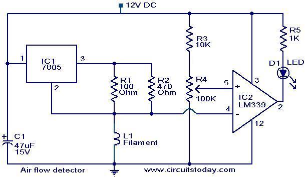
The filament of an incandescent bulb serves as the sensing component of the circuit. When there is no airflow, the resistance of the filament is low. In contrast, when airflow is present, the resistance decreases because the moving air...
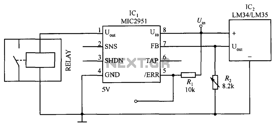
The circuit depicted in the figure utilizes a thermal protection system featuring the MIC2951 component. The temperature threshold can be adjusted by modifying resistor R2. The thermal protection circuit employing the MIC2951 is designed to monitor and regulate temperature within...
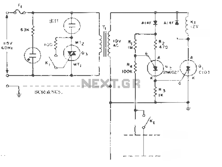
This circuit is designed to maintain the liquid level between two fixed points. By transforming the K1 contacts off the case, it can perform filling or extraction operations in two modes. The load can be either an AC motor...
Color sensing using a camera and a sufficiently powered processor that runs image histogram logic (or similar algorithms) can reliably determine the presence of specific colors. However, alternatives that are significantly more cost-effective for detecting the presence or absence...
The LM358 consists of two independent, high-gain operational amplifiers in a single package. An important feature of this integrated circuit (IC) is that it does not require separate power supplies for the operation of each comparator, accommodating a wide...
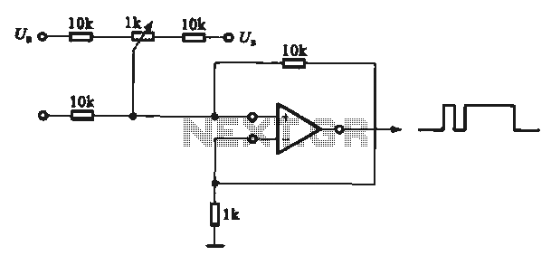
This circuit demonstrates the application of various types of pulse signal generating circuits using operational amplifiers. The circuit utilizes operational amplifiers (op-amps) to create different forms of pulse signals, which are essential in many electronic applications, including waveform generation, timing...