
The triangular wave carrier generator circuit diagram

The triangular wave generator circuit described employs two operational amplifiers configured in a feedback loop to produce a stable triangular waveform. The use of operational amplifiers is advantageous due to their high input impedance and low output impedance, which facilitate effective signal processing.
R62, the offset adjustment resistor, plays a crucial role in calibrating the output waveform to ensure that it oscillates symmetrically around a desired voltage level. By adjusting R62, the user can fine-tune the baseline voltage of the triangular wave, accommodating variations in power supply or desired output levels.
R27, the peak adjustment resistor, allows for the modification of the amplitude of the triangular waveform. This adjustment is essential for applications that require specific voltage levels or for interfacing with other circuit components that may have varying input requirements.
The inclusion of a switch to select different resistances enhances the circuit's versatility. By changing the resistance values, the frequency of the output triangular wave can be altered. This feature is particularly useful in applications such as signal modulation, waveform generation for testing purposes, or in audio synthesis where different frequencies are needed.
Overall, this triangular wave circuit is designed for flexibility and precision, making it suitable for various electronic applications where a stable and adjustable waveform is required. As shown by the triangular wave circuit composed of two OP, R62 is OFFSET adjustment, R27 for the adjustment of the peak, with the switch to select different resistance obtaine d triangular waves of different frequencies.
Related Circuits
The LM1036 is a DC controlled tone (bass/treble), volume and balance circuit for stereo applications in car radio, TV and audio systems. An additional control input allows loudness compensation to be simply effected. Four control inputs provide control of...

This circuit is based on a Philips class-H audio amplifier integrated circuit (IC) and can deliver 36W RMS or 70W music power, all from a 13.8V supply. The Mighty Midget Amplifier is capable of providing approximately 36W RMS continuous...
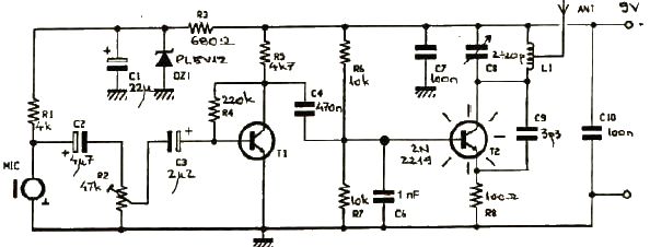
This FM transmitter electronic project operates in the FM band with a transmission power of approximately 250 mW. The circuit is straightforward and utilizes common transistors and electronic components. The T1 transistor, which may be a BC107, BC171, or...
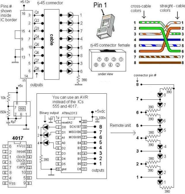
This LAN tester circuit was originally designed by Vassilis Stergiopoulos. It features two optional designs. The first design utilizes two main integrated circuits: the timer IC555 and the decade counter 4017. The second design is based on the microcontroller...
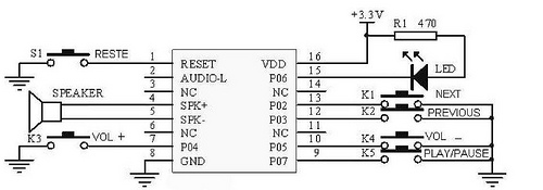
This tutorial focuses on the MP3 mode of the WTV020SD-16P module. With this straightforward circuit, AD4 format music files can be played. A video demonstration of this simple project is available at the end of the article. The project...

Any type of flashing light on the main brake lights is prohibited and illegal in most states of the U.S.A. Verification is being conducted for the same in Canada. Meanwhile, using this circuit is at one's own risk, with...