
Variable astable frequency oscillator
The circuit described utilizes a 555 timer IC configured in astable mode to generate a square wave output. The frequency of the output signal can be adjusted using a potentiometer, providing versatility for various applications such as tone generation, clock pulses, or signal modulation. The configuration allows for a frequency range from a few hertz up to several kilohertz, depending on the selected resistor and capacitor values.
In this setup, resistor R1 and potentiometer R2 determine the timing intervals for the charging and discharging cycles of the capacitor C. The relationship between the components is defined by the frequency formula:
\[ f = \frac{1}{0.69 \times C \times (R1 + 2 \times R2)} \]
This indicates that increasing the capacitance (C) or the resistance values (R1 and R2) will decrease the frequency, resulting in a longer period of the square wave.
The duty cycle, which defines the proportion of time the signal is high versus low, is calculated using the formula:
\[ \text{Duty Cycle (\%)} = 100 \times \frac{(R1 + R2)}{(R1 + 2 \times R2)} \]
For applications requiring a close to 50% duty cycle, it is advisable to keep R1 significantly smaller than R2. However, R1 should not be less than 1kΩ to ensure stable operation of the timer. Typical values may include R1 in the range of kilohms and R2 in the range of megaohms, allowing for fine-tuning of the frequency and duty cycle.
To achieve lower frequency outputs, the capacitor value may be increased beyond the standard 0.01µF, which will further extend the timing intervals. Careful selection of R1, R2, and C will enable the user to customize the circuit's performance to meet specific requirements. Overall, this simple yet effective circuit demonstrates the versatility of the 555 timer IC in generating adjustable frequency square waves.This is a very simple circuit utilising a 555 timer IC to generate square wave of frequency that can be adjusted by a potentiometer. With values given the frequency can be adjusted from a few Hz to several Khz. To get very low frequencies replace the 0.01uF capacitor with a higher value. The formula to calculate the frequency is given by: 1/f = 0.69 * C * ( R1 + 2*R2) The duty cycle is given by: % duty cycle = 100*(R1+R2)/(R1+ 2*R2) In order to ensure a 50% (approx.) duty ratio, R1 should be very small when compared to R2. But R1 should be no smaller than 1K. A good choice would be, R1 in kilohms and R2 in megaohms. You can then select C to fix the range of frequencies. 🔗 External reference
Related Circuits
A 2N366 is configured as an audio feedback oscillator using an audio transformer. Adjust R1 for proper operation and the desired audio note. The circuit utilizes a 2N366 transistor, which is a general-purpose NPN transistor, serving as the primary active...
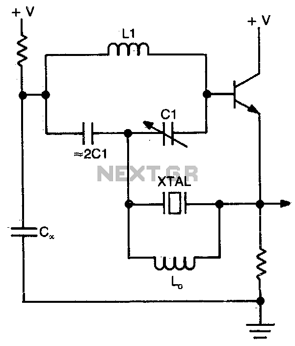
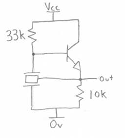
This circuit operates at or near series resonance. It is a well-designed circuit with no parasitics. It is easy to tune and has good frequency stability. The circuit in question utilizes series resonance to achieve optimal performance. At series resonance,...
There is a significant amount of vintage amateur equipment that many enthusiasts have chosen to restore and rejuvenate. Although many early amateur transceivers operate effectively, they typically lack a digital readout and depend on analog dials for tuning. The...
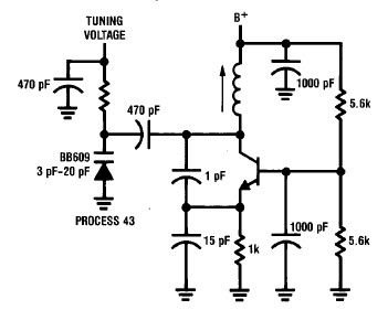
A simple high-efficiency Colpitts oscillator is utilized in higher frequency ranges, specifically above 50 MHz. Colpitts oscillators are preferred as stray circuit capacitance is in parallel with the desired feedback capacitance, preventing undesirable spurious resonances that may occur with...
A ceramic resonator can be utilized to construct an oscillator. A single digital inverter can be employed to create a Pierce oscillator. To design a Pierce oscillator using a ceramic resonator and a digital inverter, the following components and configurations...
An alternative method for utilizing operational amplifiers (op-amps) to regulate a power supply is illustrated below. The power transformer necessitates an additional winding to provide the op-amps with a bipolar voltage of +/- 8 volts. This negative voltage is...