
Overtone crystal oscillator
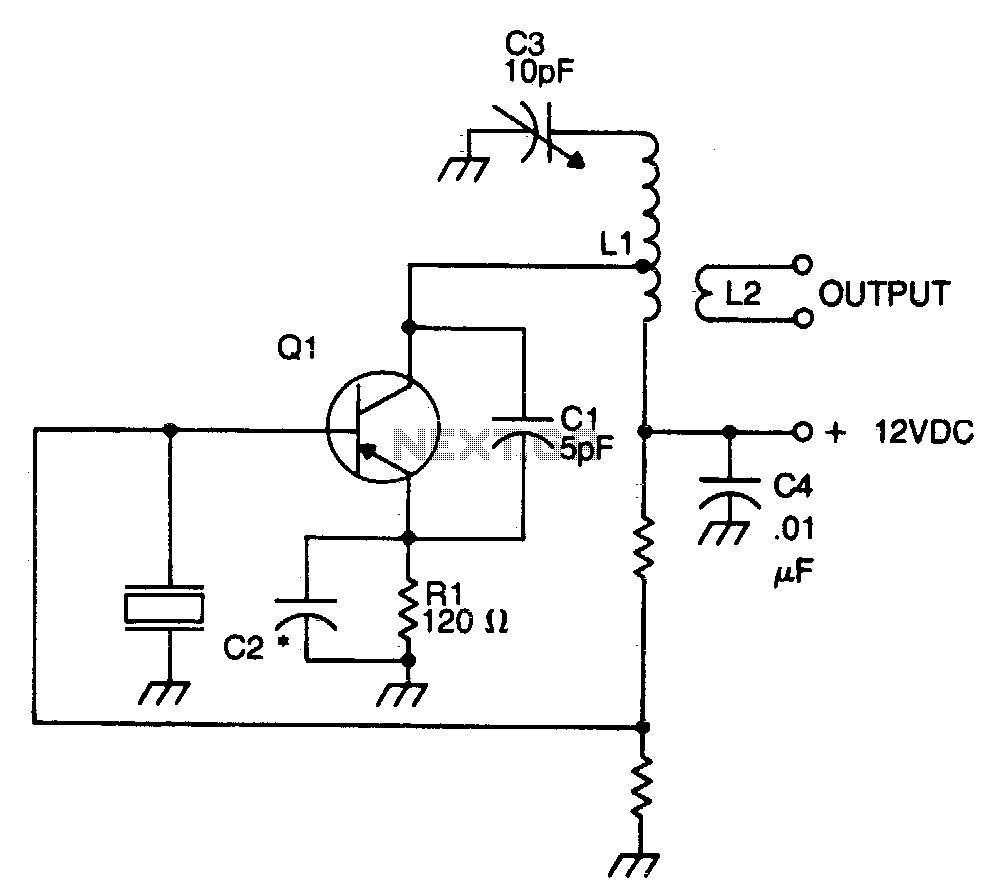
The circuit utilizes a crystal oscillator configuration, where the crystal serves as a frequency-determining element, establishing stable oscillation at its resonant frequency. The connection of the crystal between the base and ground provides a negative feedback mechanism essential for maintaining oscillation. Capacitor C1 is crucial for improving the feedback loop, compensating for the inherent capacitances present in the transistor, which can affect oscillation stability and performance. Its placement is critical; positioning it close to the transistor minimizes parasitic inductance and capacitance, thereby enhancing circuit performance.
The LC tank circuit, consisting of an inductor and capacitor, is designed to resonate at the overtone frequency of the crystal, ensuring that the oscillator operates efficiently at the desired frequency. The emitter resistor capacitor combination is designed to present a specific capacitive reactance, approximately 90 ohms, at the intended operating frequency. This value is essential for optimal performance, as it influences the gain and stability of the oscillator.
Inductor L1 features a tap that serves to match the load impedance at the collector of the transistor. This tap's placement is a critical design consideration, typically positioned about one-third from the cold end of the coil. This location is a strategic compromise, balancing the need for stability against the desire for maximum power output. The output signal is derived from the link coupling coil, L2, which operates based on transformer principles, allowing for efficient signal transfer from the oscillator circuit to the load while preserving the integrity of the signal waveform.The crystal element in this circuit is connected directly between the base and ground. Capacitor Cl is used to improve the feedback due to the internal capacitances of the transistor. This capacitor should be mounted as close as possible to the case of the transistor. The LC tank circuit in the collector of the transistor is tuned to the overtone frequency of the crystal. The emitter resistor capacitor must have a capacitive reactance of approximately 90 ohms at the frequency of operation.
The tap on inductor Ll is used to match the impedance of the collector of the transistor In most cases, the optimum placement of this tap is approximately one-third from the cold end of the coil. The placement of this tap is a trade-off between stability and maximum power output. The output signal is taken from a link coupling coil, L2, and operates by transformer action. 🔗 External reference
Related Circuits
An oscillator can be constructed using an LC (inductor-capacitor) tank circuit. By varying the capacitance of the capacitor in the LC tank circuit, the frequency of the oscillator can be adjusted. An LC tank circuit serves as a fundamental building...

This circuit is designed to be housed in a compact plastic or preferably metal enclosure, powered by a 9V battery. It features a level control, a male XLR connector (similar to those used in microphones), and a switch. The...
Hand and body motions in proximity to the sensing antennas produce frequency changes in a Hartley oscillator operating at approximately 750kHz. The signal from this variable oscillator is mixed with a constant reference frequency in a ring modulator and...
A 52 MHz third overtone crystal typically has a series resonance impedance of 30 ohms as per manufacturer specifications. The crystals utilized in the prototypes exhibit nearly ten times lower series resistance but are significantly more expensive. An oscillator...
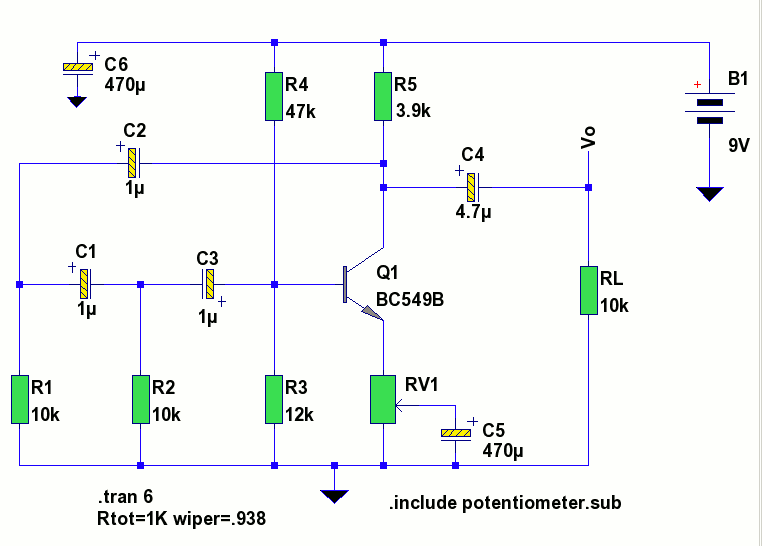
A low-frequency test oscillator designed for testing tone controls and conducting experiments. The low-frequency test oscillator serves as a versatile tool in audio engineering, particularly for evaluating tone control circuits and facilitating various audio experiments. This device generates sinusoidal waveforms...
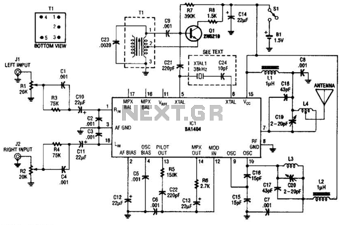
In this application, a BA1404 is utilized to generate an FM MPX baseband signal. This signal modulates a crystal oscillator (Q3) through a dual varactor series modulator. This transmitter can be used to play CD audio on an existing...