
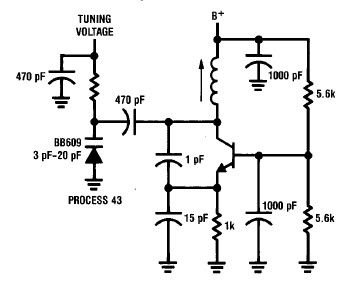
variable Hartley oscillator

The circuit operates based on the detection of hand and body motions near the sensing antennas, which influence the frequency of a Hartley oscillator tuned to approximately 750 kHz. This oscillator generates a variable frequency signal that is mixed with a constant reference frequency in a ring modulator. The output from the ring modulator is then processed through a low-pass filter, which effectively isolates the difference between the variable and reference frequencies, ensuring that only the desired signal is retained for further processing.
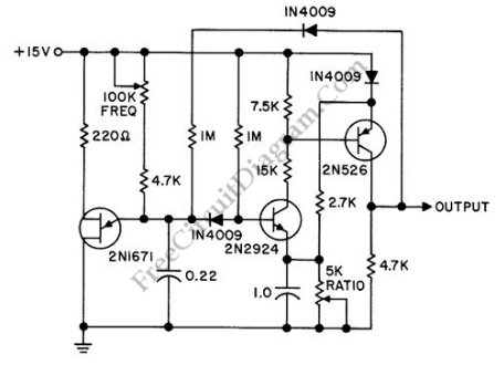
The design incorporates duplicate sensing circuitry for both pitch and volume control, allowing for independent manipulation of each parameter. The output from the ring modulators is amplified using discrete transistor amplifiers, which also contribute additional low-pass filtering due to feedback capacitors connected from the collector to the base. This configuration enhances the stability and fidelity of the output signals.
The pitch sensing circuitry produces a sine wave output that is directed to a Voltage Controlled Amplifier (VCA) for volume processing. To convert the fully filtered sine wave signal into a square wave, a Schmitt trigger is employed. This square wave is then differentiated to create narrow pulses, which are subsequently integrated to generate control voltages. The Volume Control Voltage derived from this process acts as the control signal for the internal VCA.
The front panel includes a "Timbre" control that allows the user to blend sine and square wave inputs into the VCA. The VCA itself is constructed from discrete transistors and a single-stage operational amplifier, with gain structures designed to induce distortion at maximum volume settings, adding a dynamic character to the audio output.
Moreover, the Volume Control Voltage is further differentiated to yield a Velocity Control Voltage, which is routed to the differential amplifier input of the VCA. This arrangement facilitates asymmetrical distortion effects in response to rapid changes in volume, enhancing the expressive capabilities of the device. The Velocity Control Voltage is also processed through another Schmitt trigger, generating gate and S-trigger outputs, which can be utilized for additional control functions or interfacing with other devices in a modular setup.Hand and body motions in proximity to the sensing antennas produce frequency changes in a Hartley oscillator operating at approximately 750kHz. The signal from this variable oscillator is mixed with a constant reference frequency in a ring modulator and the result passed through a single pole of low pass filter to leave only the difference between the variable and reference oscillator frequencies.
The sensing circuitry is duplicated for Pitch and Volume sensor antennas. The output of the ring modulators is boosted in level by discrete transistor amps which also provide a second pole of low pass filtering because of the the feedback capacitors from collector to base. The sine wave output of the pitch sensing circuitry is routed to the VCA () for volume processing. The fully filtered signal is converted to a square wave by a Schmitt trigger, then differentiated to produce narrow pulses which are integrated to produce control voltages. The Volume Control Voltage is used as the control signal for the internal VCA. The front panel "Timbre" control allows a blend of sine and/or square wave to serve as the input to the VCA which consists of discrete transistors and a single stage opamp.
VCA gain structures are arranged so the stage will distort when Volume is set to max. The Volume Control Voltage is differentiated to produce a Velocity Control Voltage. Velocity CV is also routed to the diff. amp input of the VCA to produce asymmetrical distortions in response to rapid volume changes. (see Panel Controls). The Velocity CV is thresholded by a Schmitt trigger to produce a gate and S-trigger outputs. 🔗 External reference
Related Circuits
RC oscillators utilize resistors and capacitors to produce low or audio-frequency signals. Therefore, they are often referred to as audio-frequency (A.F) oscillators. RC oscillators are fundamental circuit designs utilized in various applications for generating periodic waveforms, particularly in the audio...
The multiplication operation required to generate a signal with a frequency equal to the difference of the input frequencies can be implemented in various ways. A multiplied signal typically appears when two signals are added and subsequently processed through...
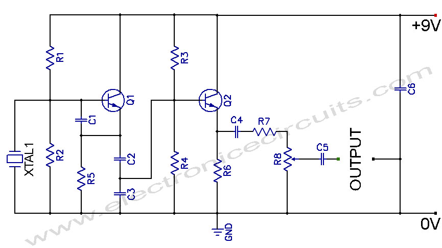
Crystal Controlled Oscillator Circuit. This general-purpose signal source is highly effective in signal-tracing applications. The output level is adjustable. The crystal-controlled oscillator circuit is designed to provide a stable and precise frequency output, which is essential for various electronic applications,...
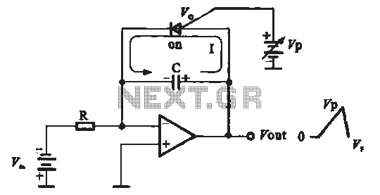
A sawtooth voltage-controlled oscillator operates by first generating a negative potential maximum at the output of the comparator. This output is then fed to the inverting input terminal through resistor R1, which is part of the relaxation oscillator. The...
A simple high-efficiency Colpitts oscillator is utilized in higher frequency ranges, specifically above 50 MHz. Colpitts oscillators are preferred as stray circuit capacitance is in parallel with the desired feedback capacitance, preventing undesirable spurious resonances that may occur with...
A discrete oscillator circuit illustrated in the schematic diagram below is a variable duty cycle and variable frequency oscillator, which can be utilized to generate various output waveforms. The discrete oscillator circuit is designed to produce oscillations with adjustable frequency...