
Pattern Generator For Radio Direction Finding Circuit
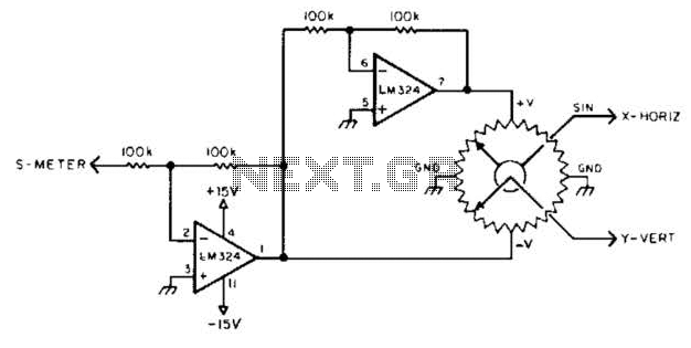
In this system, the sine-cosine potentiometer serves as a critical component that translates the angular position of the antenna into corresponding sine and cosine voltages. As the antenna is rotated to various positions, the potentiometer outputs vary, producing two voltage signals: one representing the sine of the angle and the other representing the cosine of the angle. These voltages are essential for determining the phase and amplitude of the incoming radio signal.
The directional antenna captures the radio waves, and the voltage sample derived from the received signal is processed to determine its magnitude. This voltage is usually scaled to ensure that it can be accurately compared with the outputs from the sine-cosine potentiometer. The combined information from the potentiometer and the received signal allows for a comprehensive representation of the signal's characteristics.
The display mechanism, which could be an analog or digital interface, presents the polar quantities visually, enabling users to assess both the strength and direction of the signal easily. This setup is particularly useful in applications such as radio direction finding, where understanding the orientation and intensity of signals is crucial for effective navigation and communication. In order to display polar quantities (magnitude and direction of a received radio signal), a sine and cosine voltage proportional to an angle (antenna direction) is needed. In this case, a sine-cosine potentiometer coupled to a directional antenna and a sample of a voltage proportional to received signal is used to display
relative magnitude and direction of a received signal. 🔗 External reference
Related Circuits
Unique applications of the 567 tone/frequency decoder IC include a pulse generator with a 25% duty cycle (active factor). This signal generator produces a specific output. The 567 tone/frequency decoder IC is a versatile component widely utilized in various electronic...
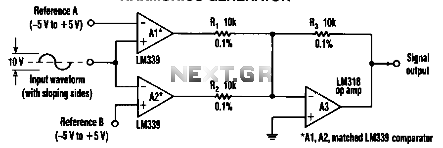
A simple frequency multiplier consists of two comparators and a summing amplifier that generate differential harmonic spectra. This circuit is capable of extracting harmonics from various waveforms, including sine, triangle, sawtooth, or other sloped waveforms. When a sloped-input waveform...
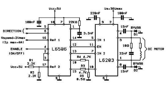
The L620x is a monolithic full bridge switching motor driver implemented using the new Multipower-BCD technology. This technology enables the integration of multiple isolated DMOS power transistors along with mixed CMOS/bipolar control circuits. The L620x series includes various versions:...
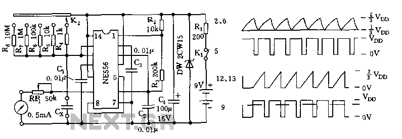
The tester comprises a dual time base circuit using a 556 timer and various RC components. The right side of the circuit features the 556 timer (556 1/2) along with resistors R2, R3, capacitors C2, C3, and additional components...
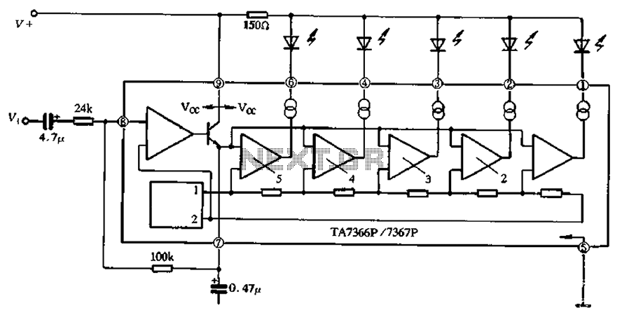
The TA 7366/7367 is a commonly used single display driver circuit manufactured by Toshiba Corporation. It features a 5 LED driver circuit and is designed in a 9-pin single in-line plastic structure. The circuit configuration includes an operational amplifier...
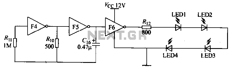
Gates F4, F5, and F6 together form a low-frequency oscillator that drives high-brightness light-emitting diode (LED) flashes. The light-emitting diodes may be arranged around the booth seat for decorative purposes. The automatic referral machine is used prior to operation...