
555 Composition with Watchdog circuit
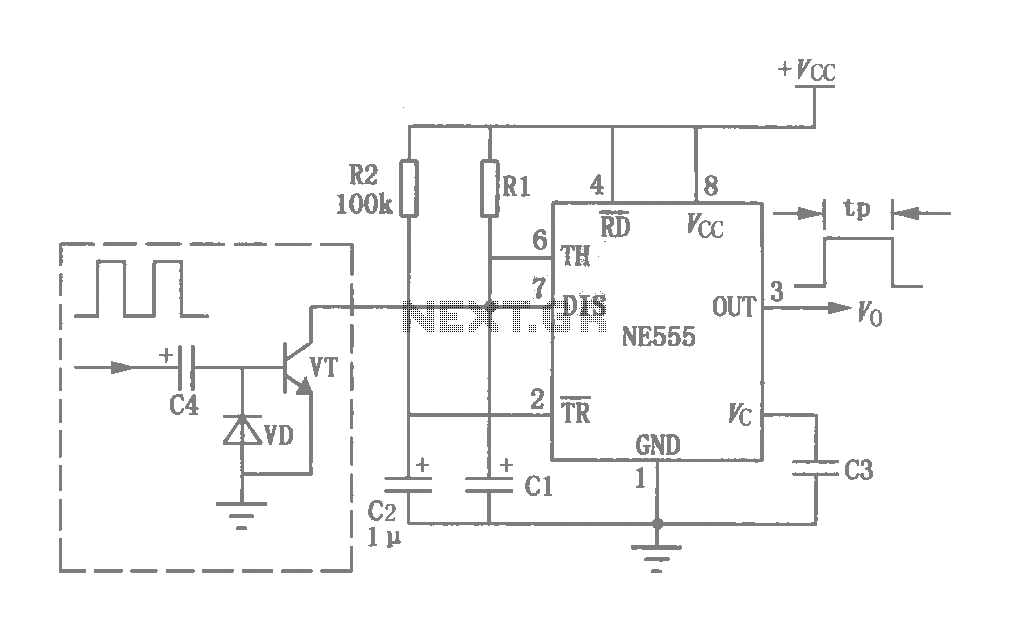
The power-delay control circuit operates by utilizing a resistor (R1) and a capacitor (C1) to establish a time constant that governs the delay period. When power is applied, the capacitor charges through the resistor, and the time taken for the capacitor to reach a certain voltage level dictates the delay time. This characteristic can be critical in applications where a delayed response is required, such as in power-up sequences or in systems that need to prevent immediate activation of components after power is applied.
The integration of a watchdog circuit enhances the functionality of the basic power-delay circuit. The watchdog circuit serves as a monitoring mechanism that ensures the system operates within predefined parameters. It can detect anomalies or malfunctions in the system's operation. If the system fails to reset or respond within a specified timeframe, the watchdog can trigger corrective actions, such as resetting the system or activating an alarm. This feature is particularly beneficial in applications where system reliability is paramount, such as in embedded systems, industrial controls, or safety-critical applications.
In a typical schematic, R1 and C1 would be connected in series, forming an RC timing circuit. The output of this timing circuit could be connected to a microcontroller or another control logic device, which would take action based on the voltage level across the capacitor. The watchdog circuit would typically include a timer and a reset mechanism that monitors the operation of the primary circuit. If the timer exceeds its limit without receiving a reset signal from the monitored system, it would initiate a predefined response to ensure safe operation.
Overall, this circuit design combines delay functionality with monitoring capabilities, making it suitable for a variety of applications that require both timing control and system oversight.This circuit was originally a type of power-delay control circuit, the delay time by the timing element Rl, C1 decision. But with the "watchdog" circuit, you can use it as a monitoring circuit for certain applications of the system.
Related Circuits
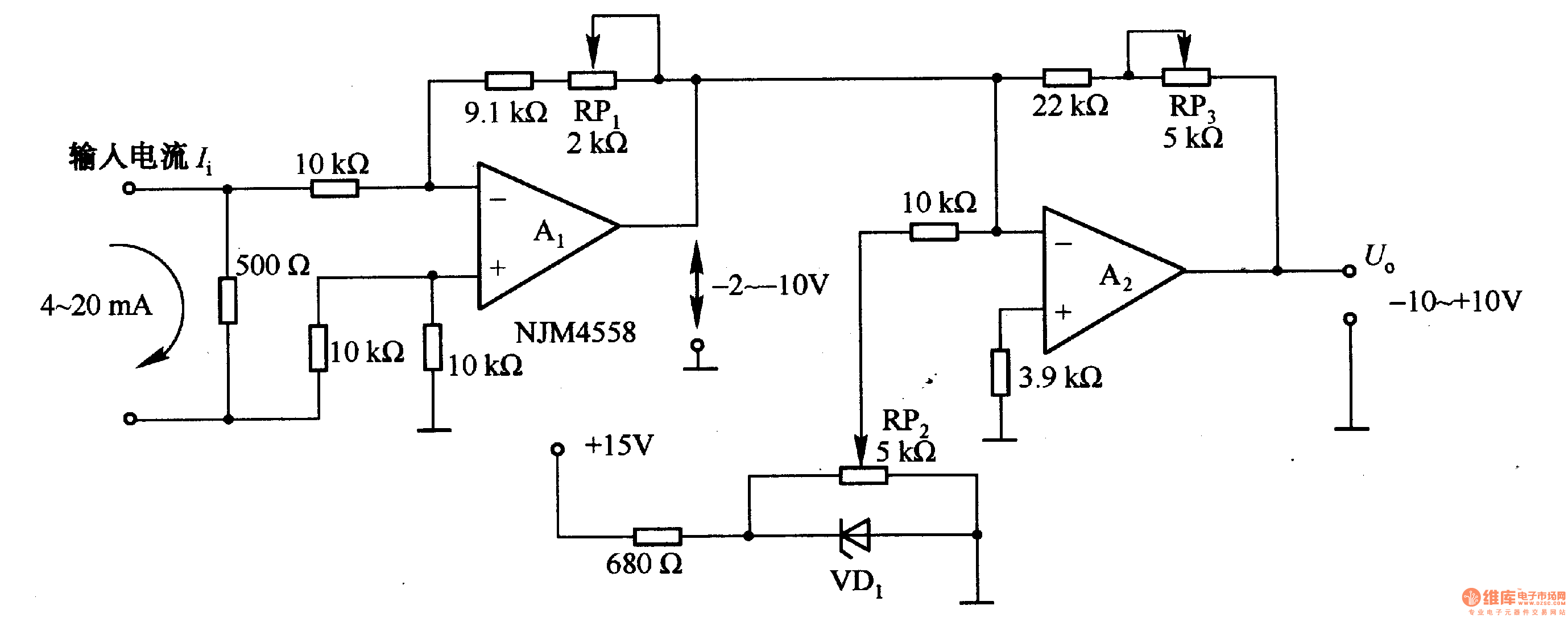
Figure 1-42 (a) is a voltage/current conversion circuit that converts a 0-10V input voltage into a 4-20mA output current. Adjusting resistor RP2 can set the input voltage (Ui) to 0V, resulting in an output current (I) of 20mA; similarly,...
A simple thermostat circuit that can control a relay to supply power to a small space heater through the relay contacts. The relay contacts must be rated above the current requirements for the heater. Temperature changes are detected by...
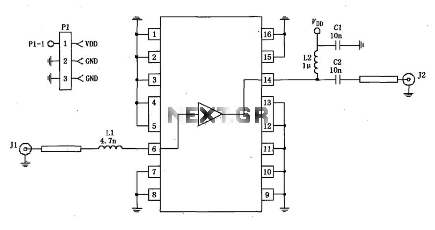
A 50-ohm impedance is illustrated in the RF2320 linear amplifier circuit, which is configured for input and output using transmission lines and inductive or capacitive components to create a matching network. The RF2320 linear amplifier circuit is designed to operate...
It is essentially a standard Hartley oscillator, with an output of +7 dBm into 50 Ohms. It is advised against adding a gate diode, as this circuit does not require it and such an addition would degrade phase noise...
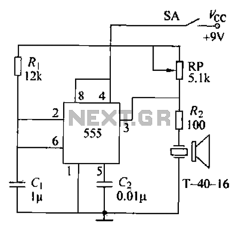
The circuit comprises an ultrasonic transmitter and a T-4 0-16 555 timer circuit. By adjusting the potentiometer RP, the frequency of the oscillation circuit can be modified. The circuit emits ultrasonic signals at a frequency of 40 kHz, with...
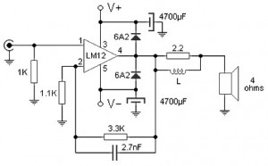
Almost all audio power amplifiers utilize integrated circuit amplifiers, such as the M12CLK, which is a power operational amplifier. This amplifier allows for an output stage that operates at an impedance of 2 ohms and provides a power gain...