
A single pulse signal generating circuit
The single pulse signal generating circuit, commonly referred to as a one-shot pulse generator, is essential in various electronic applications where precise timing and control of signal pulses are required. This circuit typically employs a combination of resistors, capacitors, and active components such as operational amplifiers or timers (e.g., 555 timer IC) to achieve its function.
In operation, the circuit is triggered by a specific input signal, which initiates the generation of a single output pulse of predetermined duration. The pulse width can be adjusted by modifying the resistor and capacitor values in the timing network, allowing for flexibility in different applications. The non-synchronous aspect of this circuit means that it does not rely on a clock signal for operation; instead, it responds directly to the input trigger.
The output pulse can be used in various scenarios, such as resetting digital counters, generating clock signals for sequential logic circuits, or controlling the timing of other electronic devices. Additionally, the circuit can include features such as output buffering to drive larger loads or integration with microcontroller systems for enhanced control and functionality.
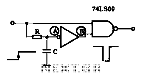
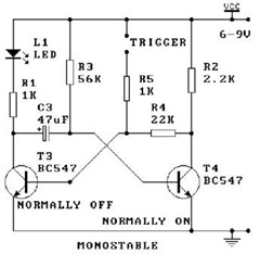
Overall, the single pulse signal generating circuit is a versatile tool in digital electronics, providing reliable and precise pulse generation for a wide range of applications.A single pulse signal generating circuit Shown as a single pulse signal generating circuit, switch contacts such as the use of such a digital signal reset signal or the stop si gnal is to be formed, this one-shot pulse generating circuit can be used. This circuit is a non-synchronous differential circuit.
Related Circuits
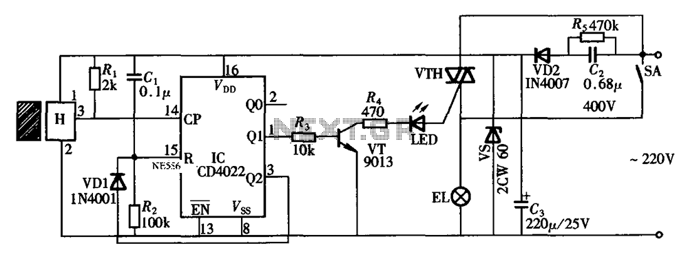
The circuit illustrated in the figure depicts an automatic bathroom light switch system. When the door is opened, the light is activated, illuminating the space. Conversely, when the door is opened again, the light turns off. The circuit comprises...
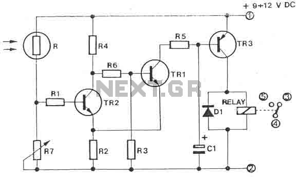
The circuit is a light switch that activates when the light intensity drops on a photoresistor. It features a straightforward construction and can be utilized in numerous applications. The photoresistor and the trimmer function as a voltage divider and...
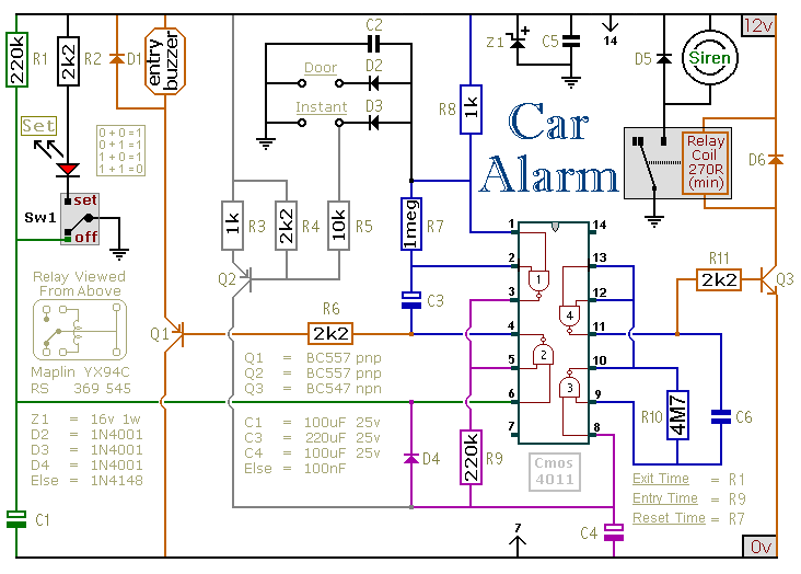
This circuit is designed to secure a vehicle at a low cost if constructed independently, making it more affordable than purchasing a commercial car alarm system. The alarm is activated by opening switch Sw1, which can be any small...

This circuit generates sine and square wave signals with frequencies ranging from below 20 Hz to above 20 kHz. The advantage of this circuit diagram is that the output frequency can be adjusted by varying the variable resistor R6. The...
The MSF transmitter transmits time data bit-by-bit over 60 seconds each minute by modulating a 60 kHz carrier frequency. It employs a continuous wave (CW) signal. Two bits are sent every second through variations in the duration and number...
An oscillator is a mechanical or electronic device that operates based on the principles of oscillation. Oscillators serve as fundamental building blocks upon which the entire structure of electronics and computers is established. An article is available that explains...