
AF locked loop circuit diagram
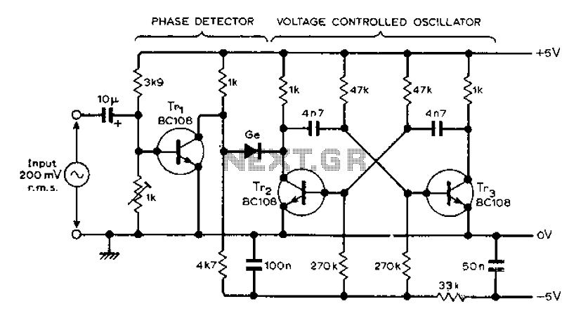
The MVBR circuit is designed to achieve phase locking by employing a two-transistor arrangement that serves as the core of the phase-locked loop. The functionality of the circuit hinges on the interaction between the voltage-controlled oscillator (VCO) and the phase detector. The VCO generates an output waveform that is subject to modulation based on the input signal frequency.
In this configuration, TR1 plays a crucial role by switching in response to the logic gate formed by the diodes. This switching action occurs during specific half cycles of the input waveform, allowing the circuit to effectively track the phase of the incoming signal. The diodes ensure that the transistors operate in the correct states, enabling the PLL to lock onto the desired frequency.
The phase detector's output is filtered to isolate the most negative phase of the waveform, which is critical for maintaining synchronization. This filtering process is essential for reducing noise and improving the stability of the phase-locked loop. The output of the phase detector is then used to adjust the frequency of the VCO, ensuring that it remains locked to the phase of the input signal.
Overall, the MVBR circuit exemplifies a straightforward yet effective implementation of a phase-locked loop, leveraging basic electronic components to achieve reliable frequency synchronization. The design is particularly useful in applications where precise timing and frequency control are required, such as in communication systems and signal processing. Circuit MVBR traditional two-transistor and other components to provide a simple phase locked loop. TR1 and diodes in the form of logic gate turns on, then half period and the VCO input waveform alternately respectively. Filtering process, the phase detector output is the most negative phase of the waveform.
Related Circuits
This amplifier is designed to be self-contained within a compact loudspeaker enclosure. It can be powered by devices such as Walkmans, Mini Discs, iPods, CD players, computers, and other devices equipped with line or headphone outputs. Typically, two units...
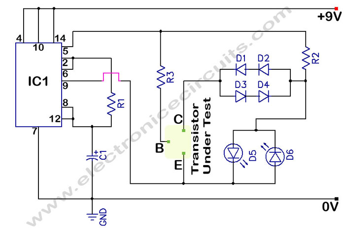
In a circuit transistor tester schematic, there is a circuit that can indicate the condition of a transistor using two LEDs. A good NPN transistor... The circuit transistor tester is designed to evaluate the functionality of both NPN and PNP...
ETl3X220 is a cost-effective single-chip transmitter that operates via RF communication. It supports up to 10 channels and is ideal for applications such as wireless mice, keyboards, and other communication devices. The main technical features include: - Analog FM...
The semiconductor thermistor is an embedded thermal protection element that is sensitive to temperature, with a temperature error of 5 degrees. It offers reliability, a small size (diameter 3.5 mm), and ease of installation, making it suitable for embedding...
A video digitizer, also known as a frame grabber, captures still picture frames from a television set, video camera, or video recorder, and transmits them to a computer for display, storage, or manipulation. This document outlines the Mark II...
The image depicts a proximity switch circuit that includes the HMC1001 Hall effect sensor, an operational amplifier (AMP04), and a light-emitting diode (LED). In this configuration, the operational amplifier functions as a comparator. When a magnet with a length...