
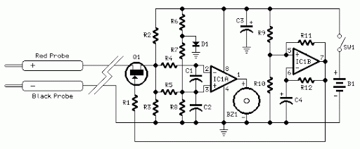
In-Circuit Transistor Tester

The circuit transistor tester is designed to evaluate the functionality of both NPN and PNP transistors by providing visual feedback through the use of two light-emitting diodes (LEDs). The schematic typically includes a power supply, resistors for current limiting, and a configuration that enables the user to connect the transistor under test.
For an NPN transistor, when the base is correctly biased, one LED will illuminate, indicating that the transistor is functioning properly. Conversely, if the transistor is faulty, neither LED will light up. The circuit can be enhanced by incorporating a switch to allow the user to choose between testing NPN and PNP transistors. In the case of a PNP transistor, the LED indicators will operate in a similar manner but with reversed polarity.
Key components of the circuit include:
1. **Power Supply**: Typically a low-voltage DC source, such as a 9V battery, is used to power the circuit.
2. **Resistors**: These are crucial for limiting the current through the LEDs to prevent damage. The values of these resistors are calculated based on the forward voltage of the LEDs and the supply voltage.
3. **Transistor Socket**: A socket or terminals are provided for easy insertion of the transistor being tested. This allows for quick swapping between different transistors.
4. **LEDs**: Two LEDs are used, one for indicating a good transistor and the other for indicating a bad one. The colors can be chosen for clear differentiation, such as green for good and red for bad.
Additional features may include a multimeter interface to measure the transistor's gain (hFE), or a buzzer that sounds an alert if the transistor is defective. The circuit can be compactly designed on a printed circuit board (PCB) for durability and ease of use.
This transistor tester is a valuable tool for electronics enthusiasts and professionals, providing a quick and effective means of diagnosing transistor health in various electronic projects.In Circuit Transistor Tester Schematic Here is a circuit that can indicate the condition of a transistor by using two LEDs. A good NPN transistor.. 🔗 External reference
Related Circuits
Acoustic check of transistor and diode junctions. Also suitable as a continuity tester. Short circuits or broken PCB tracks can be easily recognized. The acoustic check of transistor and diode junctions is a method used to assess the functionality of...
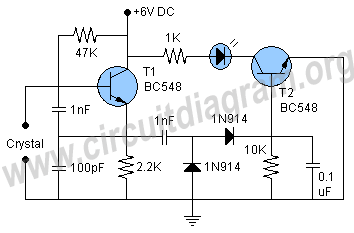
A highly beneficial project involving a crystal tester circuit, also known as an xtal tester circuit, constructed with only a few components. The circuit forms an oscillator that will only oscillate if the crystal under test is functioning properly....
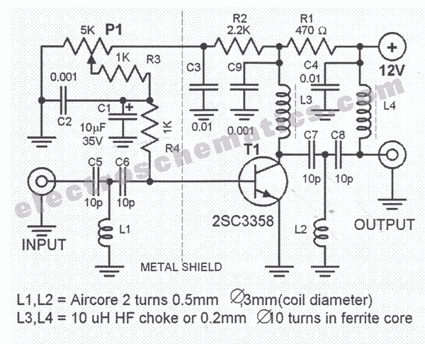
This HD TV UHF wideband amplifier (Ultra High Frequency amplifier) provides a total gain of 10 to 15 dB within the frequency range of 400 to 850 MHz, making it suitable for areas with weak television signals. To ensure...
Tools that feature the equivalent of a professional, easy-to-use, cheaper, and, more importantly, safe for use. They are designed for checking and identifying AC voltages of 220 Volt or 120 Volt. The tools mentioned are essential for ensuring electrical safety...

The electronic design features a smart battery charger schematic that utilizes only a single transistor. This design is notable as similar circuits typically employ simple integrated circuits. When the battery's charge level falls below a specific threshold voltage, the...
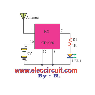
A variable frequency oscillator transistor circuit, primarily functioning as an oscillator, incorporates a crystal resonator and a varactor diode. The output is amplified, typically used for generating high-frequency signals. This 30 MHz transistor circuit features an inductor (LP) connected...