
Ramp generator circuit diagram
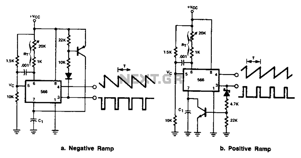
The 566 integrated circuit (IC) is a versatile component frequently used in applications requiring ramp signal generation. It can be configured to work with both positive and negative ramp generators, making it adaptable to various circuit designs. In a typical application involving a positive ramp generator, the 566's output pin 3 is utilized to drive an external transistor. This transistor acts as a switch that controls the charging and discharging of a capacitor, commonly designated as C1.
During the charging phase, the 566 generates a linear voltage ramp, which is applied to C1. The voltage across C1 increases gradually, creating a smooth ramp signal. Once the voltage reaches a predetermined level, the output pin 3 activates the external transistor, which rapidly discharges C1. This quick discharge is crucial as it allows the circuit to reset and prepare for the next charging cycle without significant delay.
The design of this circuit can be optimized by selecting appropriate values for C1 and the associated resistors, which determine the charging time constant and the ramp-up rate. Additionally, the choice of the external transistor influences the discharge speed, which is vital for high-frequency applications where rapid transitions are required. Overall, the 566 IC's ability to generate precise ramp signals makes it an essential component in various electronic applications, including waveform generators, timing circuits, and analog-to-digital converters. Circuit Description: The 566 can be connected to either positive or negative ramp generator. For positive ramp generator, the external transistor driven by the output pin 3, at the end of charging, quick to discharge C1, so you can immediately start charging again.
Related Circuits
The circuit depicted in Figure 3-121 illustrates the key component of an electromagnetic holding brake, which consists of an electromagnetic brake solenoid primarily made up of two parts: the iron core and the shoe brake components. When power is...

A voltage-controlled oscillator (VCO) operates similarly to a voltage-to-frequency converter (VFC). Its output frequency is determined by a control voltage input. In the circuit diagram, 'd' represents the amplifier input voltage, which is set to 0.6V, while 'h' denotes...
The electronic components designed by conventional electronic bonsai create a sparkling and brilliant atmosphere in the living room, enhancing the joys and pleasures of life. The selection of components includes IC1 to IC4, which consist of two pairs of...
An effective domestic alarm system is most effective when it never activates, and the best way to achieve this is to create the illusion that the premises are occupied. Most burglaries are committed by petty thieves who seek simplicity...
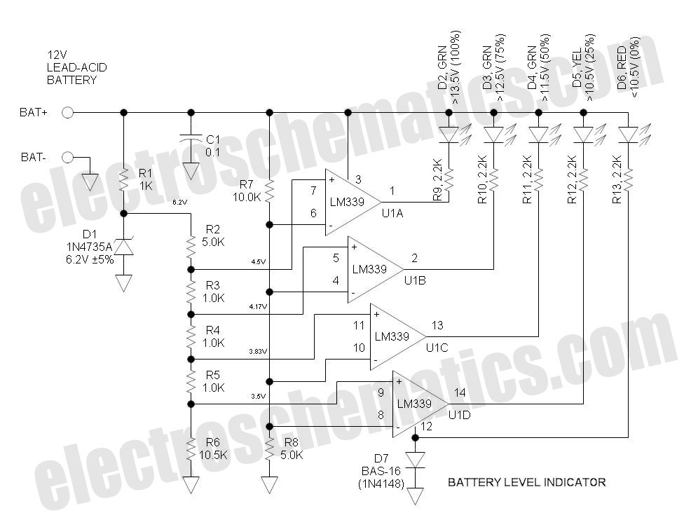
This battery level indicator features five LEDs that illuminate progressively as the voltage increases: Red indicates power connection (0%), Yellow signifies voltage greater than 10.5V (25%). The battery level indicator circuit utilizes a series of five light-emitting diodes (LEDs) to...
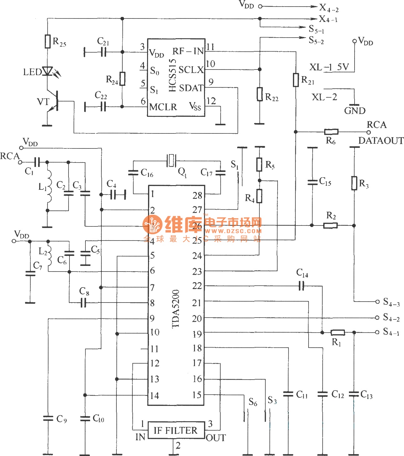
The TDA5200 is a low-power, single-chip ASK superheterodyne receiver circuit. It operates within two frequency blocks: 868 to 870 MHz and 433 to 435 MHz. This circuit is highly integrated, requiring minimal external components while offering excellent functionality. It...