
Square transform circuit diagram

The described circuit leverages the non-linear characteristics of diodes in conjunction with an operational amplifier to achieve a square-law response to input signals. The operational amplifier serves as a high-gain amplifier, which enhances the output signal proportional to the input signal's square.
In this configuration, the resistor-diode network is pivotal. The diodes, with their varying turn-on voltages, create a scenario where different segments of the input voltage are processed differently, leading to a non-linear output. When the input voltage is low, only the diode with the lowest turn-on voltage conducts, while as the input voltage increases, additional diodes begin to conduct, effectively decreasing the overall impedance of the network.
The resistor values in the network must be chosen carefully to ensure that the desired square-law characteristics are achieved over the intended range of input voltages. This involves calculating the expected voltage drops across each diode and setting the resistor values to maintain the appropriate gain for the operational amplifier.
Furthermore, the operational amplifier should be configured in a non-inverting mode to ensure that the output voltage is always positive, which aligns with the square-law function. Feedback components may also be included to stabilize the gain and improve linearity across the input voltage range.
This square-law converter circuit finds applications in a variety of fields, including signal processing and analog computing, where it is essential to convert signals in a non-linear fashion. The design must account for temperature variations and diode characteristics to ensure consistent performance. Proper layout and component selection will enhance the reliability and accuracy of the circuit, making it suitable for precision applications. At the input of the operational amplifier plus a resistor - diode network can be constructed square-law function conversion circuit. Resistor - diode network and form a voltage divider with the input voltage changes, the partial pressure of having different coefficients. Since the three diodes (VD1 ~ VD3) have different turn-on voltage, so as the input signal increases, the overall network impedance decreases, the results of the operational amplifier gain is increased. The resistance - the relationship between input and output diode network network, with an approximate square law characteristic, therefore, the whole forming a square-law converter circuit.
Related Circuits
Due to the recent launch of Cranial Electrotherapy Stimulation (CES) portable devices in Europe, a similar circuit has been designed for hobbyists. CES is a widely used method for electrically enhancing brain function and has been prescribed by medical...
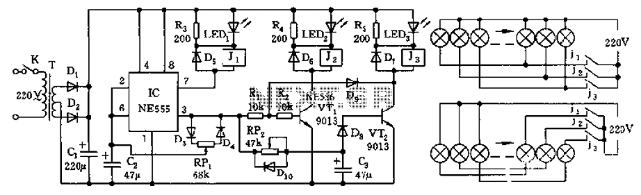
The controller features a buck rectifier circuit utilizing a 555 multivibrator, designed for controlling approximately 220V, 5W low-power parallel lights or 6 to 12V small bulb series. The 555 timer, along with components D3, D4, RP1, and C2, forms...
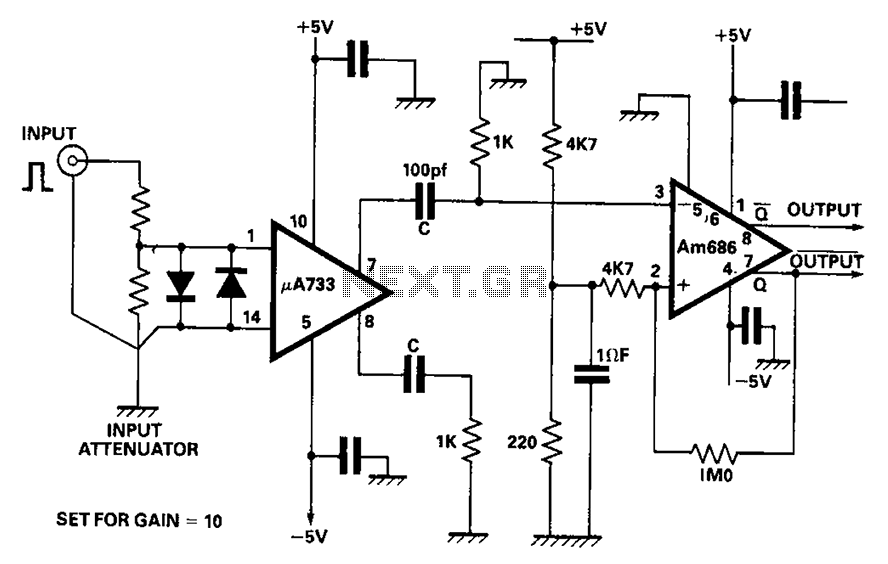
A video amplifier output arrives at a differentiation stage before the Schottky comparator. The typical propagation delay is reduced to 10 ns. The output pulse width is determined by the capacitance value, where C is 100 pF, resulting in...
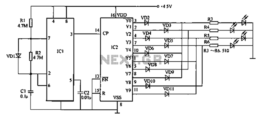
Prolonged reading or writing, maintaining a close distance between the eyes and the book, and insufficient lighting are primary contributors to decreased vision. This example describes a visual fatigue eliminator designed to alleviate eye fatigue and prevent myopia. The...
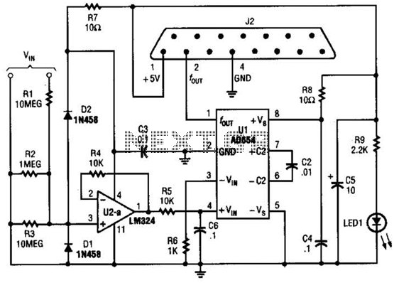
The adapter comprises a voltage-to-frequency converter integrated with a signal conditioning and protection circuit. J2 interfaces with the game port of a personal computer. Additional software references are available for use with this circuit. The voltage-to-frequency adapter functions by converting...
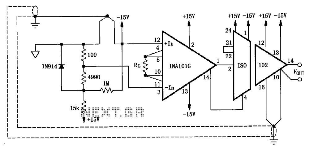
The circuit, as illustrated in the figure, consists of an ISO102 and an INA101 designed to eliminate ground loops and provide high-end cold junction compensation for a thermocouple amplifier. This configuration utilizes a K-type thermocouple to detect temperature at...