
LED Electronic roulette
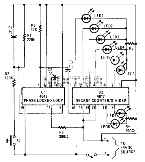
U2 progresses sequentially through its ten outputs (numbered 0 to 9) on pins 1 to 7 and 9 to 11 with each pulse received at the clock input. As each output transitions to a high state, the corresponding LED illuminates and turns off when the output returns to a low state. In this configuration, only eight outputs are utilized, providing two numbers for the spinner mechanism of the house. The circuit can be arranged to produce a sequential lighting pattern of the LEDs, or a staggered combination can be employed, allowing the LEDs to be arranged in a straight line or a circular formation.
The 4046 PLL is a versatile device that allows for modulation of frequency based on external voltage inputs, making it suitable for applications requiring precise timing and frequency control. The choice of components, such as resistors R1, R6, and capacitors C1 and C2, plays a critical role in defining the operational characteristics of the VCO, thereby influencing the overall performance of the circuit. The 4017 decade counter is designed to provide a simple way to drive multiple outputs with a single clock signal, making it ideal for applications like LED displays or indicator lights.
In practice, careful selection of the resistor and capacitor values will determine the frequency response and pulse duration of the output signal. This can lead to various visual effects depending on the arrangement of the LEDs and the timing of the pulses, enhancing the user experience in applications such as games or decorative displays. The integration of the Zener diode in the circuit ensures stable voltage levels, preventing fluctuations that could adversely affect the operation of the VCO and the subsequent output of the 4017 counter. Overall, this circuit exemplifies a practical implementation of a PLL-based timing solution with visual output capabilities.Ul (a 4046 PLL containing a voltage controlled oscillator or VCO, two phase comparators, a source follower, and a Zener diode) is used to produce a low-frequency, pulsed output of about 40 Hz. The VCO's frequency range is determined by R6 and C2, which can be altered by varying the voltage at pin 9.
The rising voltage causes the frequency to rise from zero to threshold and remain at that frequency as long as SI is closed. When SI is opened, Cl discharges slowly through Rl to ground and the voltage falls toward zero. That produces a decreasing pulse rate. The output of Ul at pin 4 is connected to the clock input of U2 (a 4017 decade decoder/driver) at pin 14 via C3.
U2 sequentially advances through each of its ten outputs (0 to 9)—pins 1 to 7, and 9 to 11—with each input pulse. As each output goes high, its associated LED is lighted, and extinguished when it returns to the low state.
Only eight outputs are used in the circuit, giving two numbers to the spinner of the house. The circuit can be set up so that the LED's lights sequence or you can use some staggered combination; the LEDs grouped in a straight line or a circle. 🔗 External reference
Related Circuits
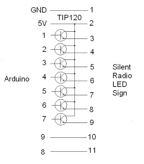
The project addresses a brightness issue with the LED display. The original design using a 4017 counter was ineffective because it lacked the capability to turn off the display while updating the shift registers. Consequently, the decision was made...
Mobile batteries typically have a lifespan of 2 to 5 years under normal usage, after which they need to be replaced. Currently, inexpensive replacement batteries are available for about $1, but these low-cost options only last 6 to 12...
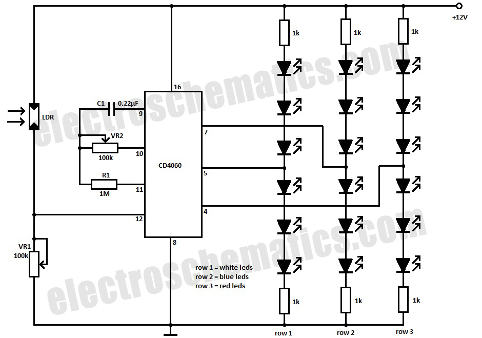
This simple Christmas LED lights decoration circuit allows for the creation of an 18 LED flasher to adorn a Christmas tree. The circuit incorporates white, blue, and red LEDs that flash in a festive pattern. The circuit is designed to...
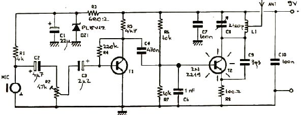
This FM transmitter electronic project operates in the FM band with a transmission power of approximately 250 mW. The circuit is straightforward and utilizes common transistors and electronic components. The T1 transistor, which may be a BC107, BC171, or...
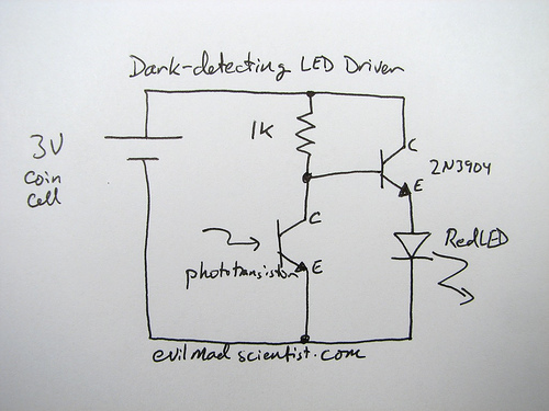
The following circuit illustrates a simple and inexpensive dark-detecting LED circuit. Features include the use of photoresistors, specifically a photocell or LDR, and an LED. This circuit utilizes a light-dependent resistor (LDR) as the primary sensing element. The LDR exhibits...

A simple LED voltmeter is designed to monitor the charge level in a lead-acid battery or tubular battery. The terminal voltage of the battery is displayed using four LED indicators. The nominal terminal voltage for a lead-acid battery is...