
Triac dimming circuit diagram
The TRIAC dimmer circuit is an effective solution for controlling the brightness of lamps and the speed of motors using phase control methods. The core components include a TRIAC, which is a type of semiconductor device that can control power. The circuit operates by delaying the phase of the AC waveform, effectively reducing the average power delivered to the load.
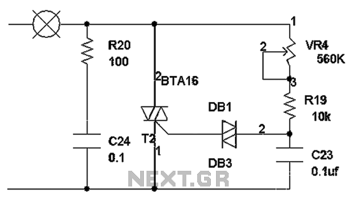
In the circuit, the lamp is connected in series with the TRIAC. The charging of the capacitor C23 through the resistors VR4 and R19 creates a time delay before the TRIAC is triggered. The values of these resistors are crucial; they determine how quickly the capacitor charges and thus influence the phase delay. A higher resistance results in a longer charging time, which in turn delays the TRIAC's conduction, reducing the power to the lamp and dimming the light.
When the voltage across C23 reaches the threshold voltage of the TRIAC, it turns on, allowing current to flow through the lamp. The lamp illuminates until the TRIAC turns off, which occurs when the current through it falls below a certain level as the AC waveform crosses zero. This on-off cycling happens rapidly, and because of the human eye's persistence of vision, the lamp appears to emit a steady light.
For applications involving inductive loads, such as motors, additional considerations must be taken into account. The inclusion of R20 and C24 helps protect the TRIAC from voltage spikes that can occur when the inductive load is switched off. This protection is essential to ensure the longevity and reliability of the circuit.
Overall, the TRIAC dimmer circuit is versatile and can be adapted for various applications, including lighting control and motor speed regulation, making it a valuable tool in electronic design. As shown for the TRIAC dimmer circuit diagram, working principle is: power, 220V lamp VR4 R19 through C23 charge. Because of two-terminal voltage capacitor is not mutated. char ging will take some time. the charging time VR4 and R19 size is determined by the smaller charge. sooner. slower. the greater the charge on the C23 when voltage of about 33V to charge when turned on. DB1 controllable. silicon is also conducting thyristor.. after a current flows through the bulb in the bulb lit up. . with the DB1 conducting voltage on C23 is completely let go. DB1 and also will be cut off.. thyristor bulb goes out. they were the same as the beginning of the cycle C23. because time is short persistence of the phenomenon of the human eye, it appears to have been light bulb bright, charge and discharge time shorter. the brighter the bulb, and vice versa. R20 C24 protects SCR. if used on a resistive load can be omitted. If it is used in the inductive load, such as would add to the motor, this circuit can also be used for motor speed control.
Related Circuits
The subwoofer is a speaker designed to reproduce low frequencies, specifically in the range of 20 Hz to 150 Hz. The electronic circuit diagram below illustrates the details of a subwoofer amplifier using the TDA1516, a 22-watt amplifier suitable...
Four simple 12V power supply circuits are designed to provide output voltages close to 12V. The first power supply circuit utilizes a BD139 transistor, a zener diode, and several passive components. Each schematic is straightforward to assemble and will...
This design outlines a simple 1 kHz square wave generator utilizing a few components and the LM3909 integrated circuit, which is beneficial for testing audio equipment. The circuit operates on a single 1.5V battery cell, producing a maximum output...
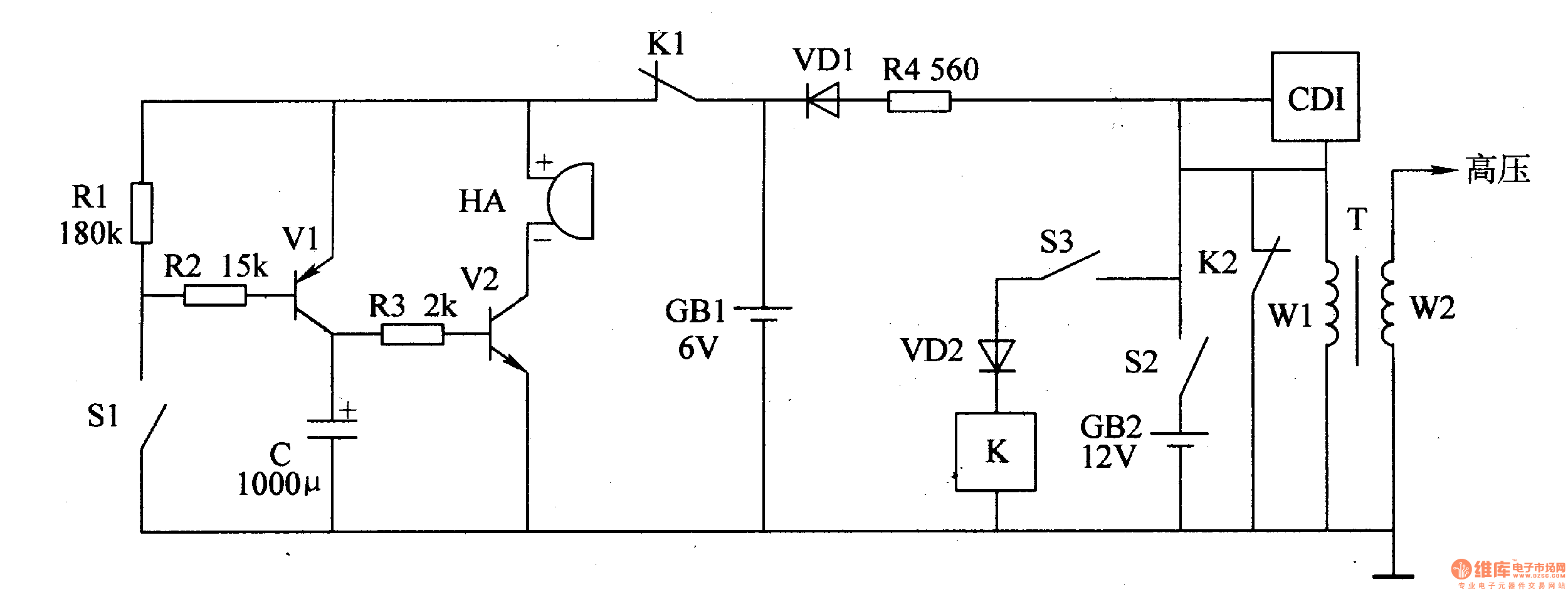
The motorcycle anti-theft alarm circuit consists of a detection alarm circuit, a charging circuit, and an anti-theft control circuit, as illustrated in figure 7-94. The detection alarm circuit includes a mercury switch (S1), resistors (R1-R3), a capacitor (C), transistors...
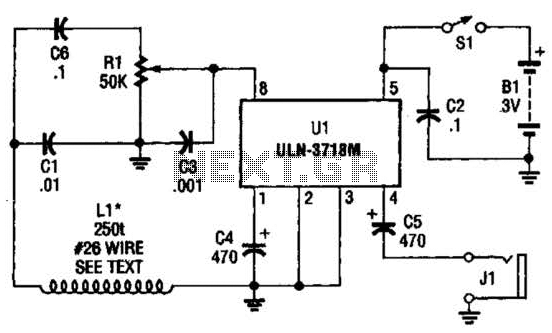
The VLF whistler receiver is designed to detect natural radio noise and signals that occur below 20 kHz. LI is a large loop antenna consisting of 250 to 300 turns of #26 gauge wire wound on a form with...
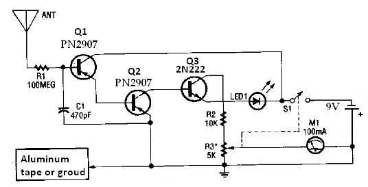
This ion detector circuit is designed to sense static charges and free ions present in the air. It is capable of detecting the presence of free ions, static electricity, or high voltage leakage. The project utilizes a short whip...