
1KHz Square Wave Generator Circuit

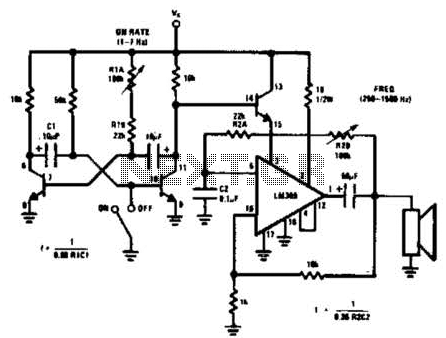
The circuit schematic consists of an LM3909 integrated circuit, which is primarily designed for generating timing signals. The LM3909 is configured in astable mode to produce a continuous square wave output at a frequency of 1 kHz. The frequency of oscillation is determined by the values of external resistors and capacitors connected to the IC. Specifically, resistors R1 and R2, along with capacitor C1, set the timing characteristics of the square wave.
The output from the LM3909 is taken from the output pin, which provides a square wave signal with a peak voltage of approximately 1.1V, suitable for interfacing with various audio equipment. The circuit is powered by a single 1.5V battery, making it portable and easy to use in various testing environments.
Potentiometer P1 is connected in such a way that it allows for the adjustment of the duty cycle of the square wave. This adjustment enables the user to modify the symmetry of the waveform, thereby affecting how long the signal remains high versus low during each cycle. Potentiometer P2 is similarly connected to control the amplitude of the output signal, allowing for fine-tuning based on the requirements of the audio equipment being tested.
Overall, this simple square wave generator circuit is an effective tool for generating test signals in audio applications and can be easily assembled with minimal components. The compact design and low power requirements make it ideal for portable testing setups.Here`s a design for a simple 1KHz square wave generator using a few components and the LM3909 that is useful for testing audio equipment. The circuit is based from the IC. It is powered from a single 1. 5V battery cell and the maximum amplitude of the output signal is 1. 1V. With P1 you can adjust the symmetry of the square wave signal and with P2 th e amplitude. This is the figure of the circuit; 🔗 External reference
Related Circuits
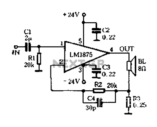
A current-sense amplifier is utilized to enhance the performance of the LM1875 current-mode amplifier circuit, as depicted in Figure 5-20. The resistor R3 and the series resistance of the speaker contribute to the current flowing through R3. This current...
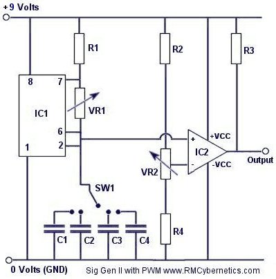
Construct a signal generator using readily available components. It should produce a square wave with variable frequency and adjustable pulse width. This device can be utilized for various applications, including DC motor speed regulation, dimming of lamps or LEDs,...
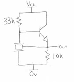
A ceramic resonator can be utilized to construct an oscillator. A single digital inverter can be employed to create a Pierce oscillator. To design a Pierce oscillator using a ceramic resonator and a digital inverter, the following components and configurations...
An LM380 audio IC is configured as a feedback audio oscillator. A transistor astable modulates this oscillator at a low frequency, which produces a siren tone. The circuit utilizes the LM380, a power audio amplifier IC, which is configured to...
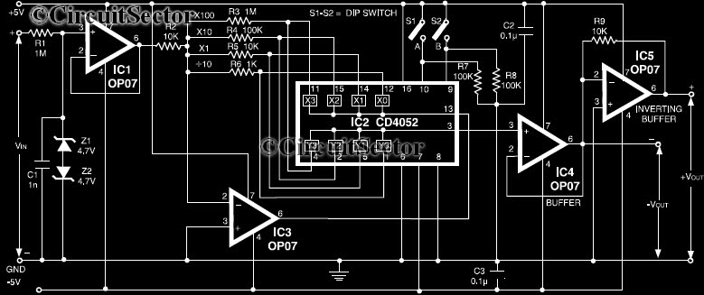
This circuit is a precision amplifier with digital control, designed for signal conditioning of low-output transducers operating in the millivolt range. The resistors R3 to R6 can be user-selected, with values ranging from 1 kilo-ohm to 1 mega-ohm, allowing...

This is an AC-powered LED flasher that can drive two high-bright LEDs directly from the power obtained from the AC lines. The high-bright LED flasher can be... The AC-powered LED flasher circuit is designed to illuminate two high-bright LEDs using...