
Switchmode PSU Protection Circuit

The described circuit serves as a protective mechanism for a DIY switching power supply intended for car amplifiers. This protection circuit is crucial for ensuring the longevity and reliability of the power supply by monitoring three critical parameters: over voltage, under voltage, and over temperature.
The over voltage protection (OVP) component typically involves a voltage sensing circuit that compares the output voltage to a predetermined threshold. When the output voltage exceeds this threshold, a signal is generated to trigger a shutdown mechanism, which can be implemented using a relay or a transistor switch to disconnect the power supply from the load.
Under voltage protection (UVP) operates similarly but focuses on ensuring that the output voltage does not fall below a certain level. This is important to prevent damage to connected amplifiers that may not operate correctly or could be damaged by insufficient voltage. A comparator can be used to monitor the output voltage, and if it drops below the set level, the circuit will again activate a shutdown mechanism.
Over temperature protection (OTP) is achieved through the use of temperature sensors, such as thermistors or integrated temperature sensors. These devices monitor the temperature of critical components within the power supply. If the temperature exceeds a safe operating limit, the circuit will trigger the shutdown to prevent thermal damage.
The design emphasizes minimal component usage, which not only reduces costs but also simplifies the assembly and increases reliability. Common components may include resistors, capacitors, operational amplifiers for voltage comparison, and a microcontroller for more sophisticated control logic. The layout should ensure that all sensing elements are placed in locations where they can accurately reflect the operational conditions of the power supply.
In summary, this protective circuit is essential for maintaining the functionality and safety of a DIY switching power supply for car amplifiers, ensuring that it can operate under a wide range of conditions without risking damage to the connected audio equipment.The circuit is designed to provide protection to a DIY switching power supply for car amplifiers by shutting down under any or all of the three modes of protection (over voltage, under voltage and over temperature) with minimal components. 🔗 External reference
Related Circuits
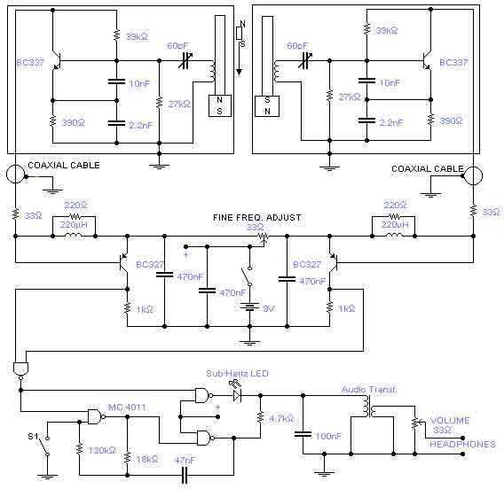
This is a rather sensitive circuit which will detect minute variations of a magnetic field, particularly the Earth magnetic field. The principle is based on an audio beat tone generated by two identical oscillators. These must be built in...
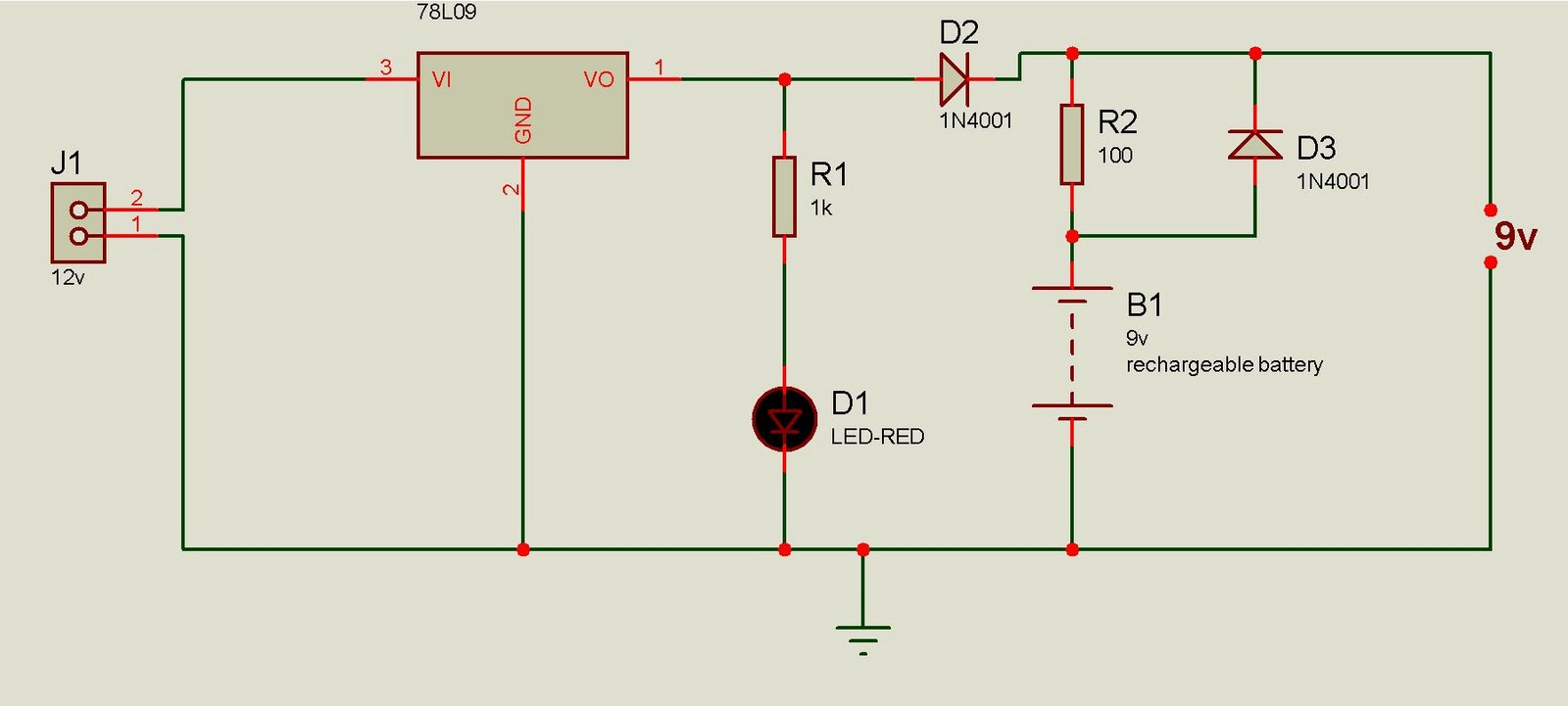
This battery backup circuit can be integrated into surveillance systems or alarm controls to provide power during mains power failures. The battery backup will immediately take over the load without any delay, and the circuit is simple to construct....

Here's PLL FM transmitter circuit from china. This circuit uses the familiar 2SC1971 for final power amplifier stage. The PLL controller of the FM transmitter use SAA1057 and PIC16F628 (download HEX file). More: If want to change the active...

The circuit operates as a light-to-sound conversion system, featuring a light electric sound conversion circuit with two simple fiber optic connectors for experimental purposes. The electrical diagram illustrates the conversion circuit, where audio signals from a radio, music player,...
Video-DVM is a very cheap DVM that shows how an output as complex as a videocomposite signal can be generated entirely in software: two I/O pins and three resistors are all the hardware required. Connected to any TV set...
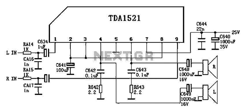
Color is often used in audio circuits like the TDA1521, which is derived from the Changhong C2191 model featuring an OTL two-channel connection. The pin functions and reference voltages for the TDA1521 are as follows: Pin 1: 11V -...